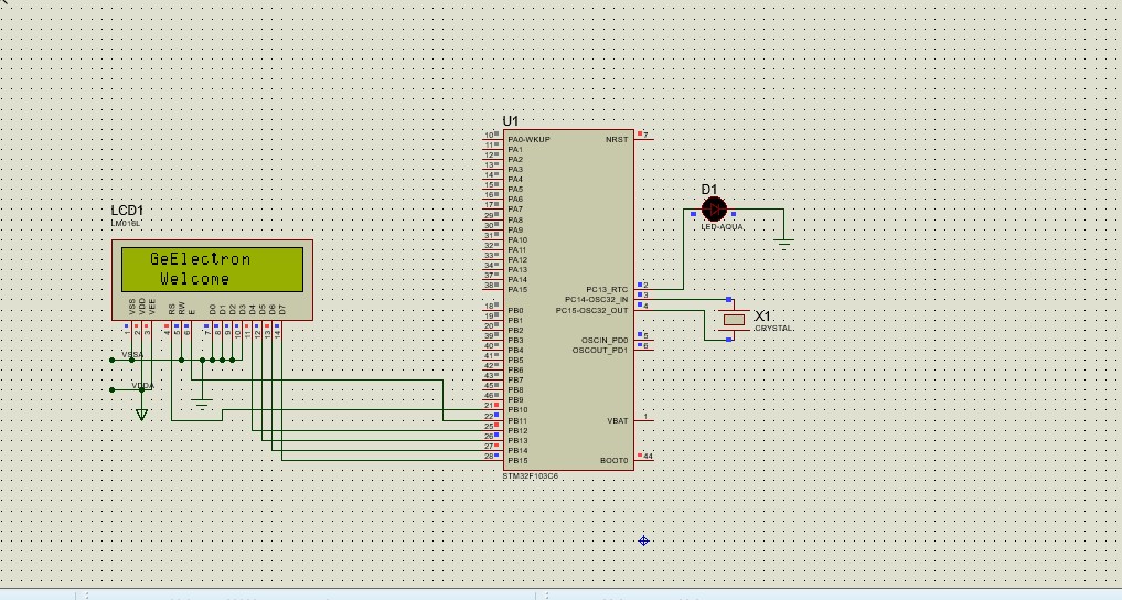
16x2 LCD Interfacing with STM32,STM32F103C6
lcd_init();

   LCD_LINE1;
  lcd_String("  GeElectron");
  LCD_LINE2;
   lcd_String("   Welcome");

  /* USER CODE END 2 */

  /* Infinite loop */
  /* USER CODE BEGIN WHILE */
  while (1)
  {
    /* USER CODE END WHILE */

    /* USER CODE BEGIN 3 */

	  HAL_GPIO_WritePin(GPIOC,GPIO_PIN_13, GPIO_PIN_SET);// LCD Enable PIN to High
	 	  	  HAL_Delay(500);
	 	  HAL_GPIO_WritePin(GPIOC,GPIO_PIN_13, RESET);
	  	      HAL_Delay(500);
	  	  //  lcd_String("Hello");

  }
  /* USER CODE END 3 */
}
LCD.c File
/*
 * lcd.c
 *
 *  Created on: Sep 30, 2023
 *      Author: Geelabs
 */
#include "stm32f1xx_hal.h"
#include "lcd.h"
#include "main.h"


extern void Delay_Us (uint16_t us);
void lcd_Strobe(void)
{

	HAL_GPIO_WritePin(GPIOB,GPIO_PIN_11, GPIO_PIN_SET);// LCD Enable PIN to High
    HAL_Delay(1);
    HAL_GPIO_WritePin(GPIOB,GPIO_PIN_11, RESET);// LCD Enable High to Low
    HAL_Delay(1);
 }

void lcd_init(void)
{

  HAL_Delay(40);
  lcd_cmd(0x03);
  HAL_Delay(5);
  lcd_cmd(0x03);
  HAL_Delay(1);
  lcd_cmd(0x03);
  HAL_Delay(10);
  lcd_cmd(0x02); // Function set --> DL=0 (4 bit mode), N = 1 (2 line display) F = 0 (5x8 characters)
  HAL_Delay(1);
  lcd_cmd(0x28);
  lcd_cmd(0x08);
  HAL_Delay(10);
  lcd_cmd(0x00);
  lcd_cmd(0x01);
  HAL_Delay(3);
  lcd_cmd(0x00);

   lcd_cmd(0x0c);            // Make cursorinvisible
   lcd_Clear();            // Clear screen
   lcd_cmd(0x6);            // Set entry Mode(auto increment of cursor)
}

void lcd_cmd(__uint16_t cmd)
{
	    HAL_GPIO_WritePin(GPIOB,GPIO_PIN_10, GPIO_PIN_RESET);
        cmd = (cmd << 8) ;
        GPIOB->ODR =  (cmd & 0xf000);
        lcd_Strobe();
        cmd = (cmd << 4) ;
        GPIOB->ODR =  (cmd & 0xf000);
        lcd_Strobe();
}


void lcd_data(__uint16_t lcd_data)
{
    HAL_GPIO_WritePin(GPIOB,GPIO_PIN_10, GPIO_PIN_SET);
     lcd_data = (lcd_data << 8) ;
     GPIOB->ODR =  (lcd_data& 0xf000)|0x400;
     lcd_Strobe();
     lcd_data = (lcd_data << 4) ;
     GPIOB->ODR =  (lcd_data & 0xf000)|0x400;
     lcd_Strobe();
   }


void lcd_Clear(void)
{
    lcd_cmd(0x01);
    HAL_Delay(5);
}

void lcd_String(const char *ptr)  // ptr pointing the address of displaying string
{
    while (*ptr)             // check weather the endo of file then exit the loop
    {
        lcd_data(*ptr++);    // Sending data to LCD_data functions
    }
}


