An External Pulse Counter Using 8051 and Dispalying on 16x2 LCD
A circuits which is used to count the external pulses And which is displaying on an 16x2 LCD display . You can simply use this project for various purpose .It is a default project for counting Purpose.

Tutorials : -
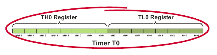
To use 16 Bit counter we need to configure some register in 8051 as follows
TMOD Register is need to configure as follows
16 bit counter Setting with timer 0
TMOD=0x05; // Giving 0x05 it configured so .
8051 has Two Timer (each has 16 bit ) i am taking here Timer 0 It has to part First 8 bit (TL)) and the second part is (TH0) .
This timer is using to store the Pulses from the external (ie it will increment up to 65535 or FFFF)
TH0 = 0; // that timer clearing
TR0 = 1 // TR0 setting to start the counting .
Done .................................
After setting the above register as said the resulted value (counting value ) will save periodically in TL0 and TH0 . That value displaying after converting it to decimal . for LCD Tutorials Go Here

Click Here