Download HereADC Reading With Internal Adc Of AVR - Atemga 32 And Displaying On LCD
According to data sheet there are 3 registers are used to works the ADC in AVR atmega 32
ie ,
1) ADMUX
2)ADSCR
3)ADC
1) ADMUX :-

It is an 8 bit Register ,each bit has some functions as follows
REFS1 & REFS0 :- is used for the reference Voltage with respect to our analog input (for resolution) to know more search this blog.
I am giving 5volt as reference so selected REFS1 = 0 & REFS0 = 1
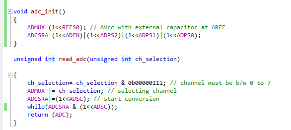
ADMUX=(1<<REFS0); // AVcc with external capacitor at AREF ,giving a high to REFS0.
MUX0-MUX4 :- it is used to select the input channel ,ie 8 analog input channel can be given so desired one selection by giving appropriate value .

ADLAR : - used to shift the resulted data (ADC Value) left or right .I am using right shift so makes as low.
.....................................................................................................................................
2) ADSCR :- ADCSRA = (1<<ADEN)|(1<<ADPS2)|(1<<ADPS1)|(1<<ADPS0);
It is also an 8 bit register .

Bit 7 used to ADC ON (ADC Turn ONing by applying a high bit )
Bit6 ADSC is used to start the conversion .and still maintain it value as high up to the conversion . after conversion it becomes low (Zero)
ADATE and ADIF is not used by me now .(not by using Intruppet
Bit 0 to bit2 is used for select ADC frequency .

 \
\
2) ADC: It is a 16 bit to 8 bit register ADCL & ADCH. By applying right shift value it is autmatically set as normal value so we can take simple value from it
eg : return (ADC);
adc_value = read_adc(ch_sec);
The program as follows . The full program can be download below including Proteus simulation file.