Here Atmega16 measuring the current and voltage by inbuilt comparator .Previous post described how to read ADC value click here . Two ADC port is used PA0/ADC0 is measuring voltage .And PA1/ADC1 is measuring current .
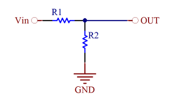
We have to measure 0 to 12 volt, but controller can only read as maximum voltage 5 volt .
Hence a voltage divider circuit used to reduce the corresponding voltage level at a mximum 5Volt.


take
Vin = 12volt
Vout = 5 volt.
Assume one of the resistor value and find out the other .
***********************************************************************************
we have to measure current ,But we cant directly measure the current . there are more technique to measure the current. we uses a shunt resistor method .
 The millivoltmeter voltage is taken and calculated by some equation and displayed as current .for more click here
For example .
According Ohm's law, 0.1 Ohm resistor under 1A current will give 0.1V voltage drop
*********************************************************************************

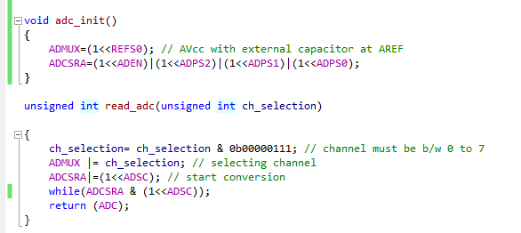
The program shown below
design circuits to feed controller for current and Volt. the whole project can be download Below including proteus file For downloading click below For Advancedtutorials click here Voltmeter Design
We have to measure 0 to 12 volt, but controller can only read as maximum voltage 5 volt .
Hence a voltage divider circuit used to reduce the corresponding voltage level at a mximum 5Volt.
take
Vin = 12volt
Vout = 5 volt.
Assume one of the resistor value and find out the other .
***********************************************************************************
we have to measure current ,But we cant directly measure the current . there are more technique to measure the current. we uses a shunt resistor method .

For example .
According Ohm's law, 0.1 Ohm resistor under 1A current will give 0.1V voltage drop
*********************************************************************************

The program shown below
* Created: 14-Oct-15 6:44:15 PM
 *  Author: Gireesh
 */
#define F_CPU 16000000UL
#include <avr/io.h>
#include<util/delay.h>
#include"lcd.h"
#include "adc.h"

int main(void)

{

 unsigned char volt[5] ,current[5];
   DDRD = 0xFF;
   int v,i;
   char ch_sec =0;
    adc_init();
    lcd_init();
 string ("G Electron ");
 LINE2
 string("Power Supply");
 _delay_ms(50);
 CLEAR
 while(1)

 {
   v =   read_adc(0);  // reading voltage
   i =   read_adc(1);  // reading voltage for current
   v = (v * 4.89 * 2.4)/10;
   i = (i * 2.92);
   i = ((i*4.89)/0.47)/10;


   if(v< 1200)
   {
   volt[0] = ((v /1000)%10)+0x30;
   volt[1] = ((v /100) % 10) + 0x30;
   volt[2] = '.';
   volt[3] = ((v/ 10) %10) + 0x30;
   volt[4] = (v % 10) + 0x30 ;


   string("Volt    : ");
   for(int i =0; i<5;i++)
  lcd_data(volt[i]); // just displaying ADC value
  string("V");
  }
  else
  {

   string("Over Voltage");
    }
 LINE2
 if(i<3100)
 {
 current[0] =((i /1000)%10)+0x30;
 current[1] = '.';
 current[2] = ((i /100) % 10) + 0x30;
 current[3] = ((i/ 10) %10) + 0x30;
 string("Current : ");
 for(int i =0; i<4;i++)
 lcd_data(current[i]);
 string("A");
 }
 else
 {

  string("Over Current");
 }
 _delay_ms(50);
 CLEAR
 }
}
Download