-->

Electronics -Notes

By

Good electronics Book Notes Tutorials

  1. Power Electronics Notes by ArunKumar
  2. ECE-VII-OPTICAL FIBER COMMUNICATION [10EC72]
  3. ECE-VII-EMBEDDED SYSTEM DESIGN 10EC74 -NOTES_1450341942484_1450360316731
  4. ECE-VII-DSP ALGORITHMS ARCHITECTURE 10EC751 -NOTES
  5. ece-vi-satellite-communications-10ec662-notes
  6. ECE-VI-OPERATING SYSTEMS 10EC65 -NOTES
  7. ece-vi-antennas-and-propagation-10ec64-notes
  8. ECE-VI-ANTENNAS AND PROPAGATION 10EC64 -NOTES
  9. EC2353 notesDigital Communication
  10. Antennas and Radiowave Propagation -Collin
  11. Prentice.The.Intel.Microprocessors.8th.Edition.0135026458
  12. advanced_communication_lab-1
  13. microprocessor-8086-lab-mannual
  14. CSE-IV-MICROPROCESSORS 10CS45 -NOTES(2)
  15. ORGANISING & STAFFING
  16. MANAGEMENT & ENTREPRENEURSHIP
  17. AN INTRODUCTION TO RADAR
  18. MANAGEMENT & ENTREPRENEURSHIP
  19. Microwave Devices and Circuits (samuel Liao)
  20. editable_Digital_Signal_Processing_Principles_Algorithms_and_Applications_T
  21. ECE-V-INFORMATION THEORY & CODING [10EC55]-NOTES
  22. ece-v-fundamentals-of-cmos-vlsi-10ec56-notes
  23. Communication-Systems—4ed—Haykin
  24. Signals_And_Systems__Schaum_
  25. CMOS-VLSI-designSignals and Systems 2Ed – Haykin – Solutions Manual
  26. Fourier Representation for four Signal Classes
  27. Fourier Representation for four Signal Classes (2)
  28. ECE-IV-SIGNALS & SYSTEMS [10EC44]-NOTES (2)
  29. Analog Communication-Prabhakar Kapula
  30. Microcontroller (www.citystudentsgroup.blogspot.com)
  31. Analog Communication (www.citystudentsgroup.blogspot.com)
  32. LInear Integrated Circuits Notes Arunkumar PDF apKART.COM
  33. EEE-III-NETWORK ANALYSIS [10ES34]-NOTES(1)
  34. ECE-IV-LINEAR ICS & APPLICATIONS [10EC46]-NOTES
  35. EEE-III-ANALOG ELECTRONIC CKTS [10ES32]-NOTES
  36. amplifiers-module-05
  37. VHDL
  38. STATE GRAPHS FOR CONTROL NETWORKS
  39. PROGRAMMABLE ARRAY LOGIC
  40. PROGRAMMABLE LOGIC DEVICES-2
  41. ECE-IV-CONTROL SYSTEMS [10ES43]-NOTES

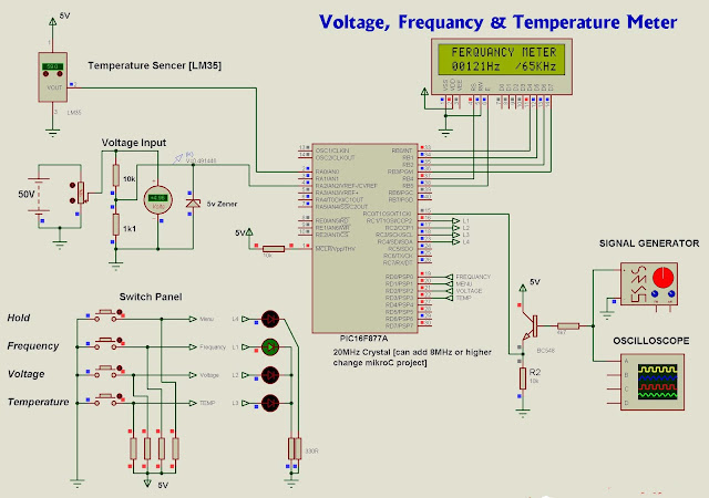
Digital Voltage Temperature And Frequency Meter Using PIC 16F877

By
Digital Voltage Temperature And Frequency Meter Using PIC 16F877

Voltage meter
Volt meter can measure dc voltages up to 50v. 5V is the maximum voltage can handle PIC microcontroller, as it is voltage divider (10K,1.1K) use for convert 50V to 5V . 5v zener diode use for safety of PIC microcontroller analog input pin.

Temperature meter 
Temperature meter can use between 00C to 1500C. But LM35 sensor can use between -550C to 1500C. Sensor’s resistant is changing opposite to temperature, as it is maximum temperature gives maximum voltage output(5v)  and minimum temperature gives minimum voltage output(0v).

                                                      Frequency meter
Theoretically, frequency meter can use up to 65KHz, that is because this circuit made by using Timer 1(16bit) of PIC microcontroller.


// LCD module connections
sbit LCD_RS at RB4_bit;
sbit LCD_EN at RB5_bit;
sbit LCD_D4 at RB0_bit;
sbit LCD_D5 at RB1_bit;
sbit LCD_D6 at RB2_bit;
sbit LCD_D7 at RB3_bit;

sbit LCD_RS_Direction at TRISB4_bit;
sbit LCD_EN_Direction at TRISB5_bit;
sbit LCD_D4_Direction at TRISB0_bit;
sbit LCD_D5_Direction at TRISB1_bit;
sbit LCD_D6_Direction at TRISB2_bit;
sbit LCD_D7_Direction at TRISB3_bit;
// End LCD module connections

unsigned short cnt;
unsigned int freq_result;
int x, y, t;

// Define Messages
char message1[] = " Hz /65KHz";
char message2[] = "FERQUANCY METER";
char Message4[] = "VOLTAGE METER";
char Message5[] = "/MAX:50V";
char Message8[] = "TEMPERATURE ";
unsigned int ADC_Value, DisplayVolt;
unsigned int tempinF, tempinC;
unsigned long temp_value;
char *volt = "00.0";
char *freq = " 0000";
char *tempC = "000.0";
char *tempF = "000.0";

void Display_Freq(unsigned int freq2write) {

freq[0] = (freq2write/10000)%10 + 48;
freq[1] = (freq2write/1000)%10 + 48;
freq[2] = (freq2write/100)%10 + 48;
freq[3] = (freq2write/10)%10 + 48; // Extract tens digit
freq[4] = freq2write%10 + 48; // Extract ones digit

Lcd_Out(2, 2, freq); // Display Frequency on LCD
}

void Display_Volt(unsigned int volts2write) {

volt[0] = volts2write/1000 + 48;
volt[1] = (volts2write/100)%10 + 48;
volt[3] = (volts2write/10)%10 + 48;

Lcd_Out(2, 2, volt); // Display Voltage on LCD
}

void Display_Temperature() {
if (tempinC/10000)
tempC[0] = tempinC/10000 + 48;
else
tempC[0] = ' ';
tempC[1] = (tempinC/1000)%10 + 48;
tempC[2] = (tempinC/100)%10 + 48;
tempC[4] = (tempinC/10)%10 + 48;
Lcd_Out(2, 1, tempC);
if (tempinF/10000)
tempF[0] = tempinF/10000 + 48;
else
tempF[0] = ' ';
tempF[1] = (tempinF/1000)%10 + 48;
tempF[2] = (tempinF/100)%10 + 48;
tempF[4] = (tempinF/10)%10 + 48;
Lcd_Out(2, 10, tempF);
}

void main() {
PORTB = 0; // Initialise PORTB
TRISB = 0b01000000; // PORTB is output
TRISA = 0b00001101; // PORTA All Outputs, Except RA0,RA3 and RA2
TRISD = 0x0F;
TRISC = 0x01;
T1CON = 3; // Timer1 on, external input RC0
TMR1IF_bit = 0; // clear TMR1IF
TMR1H = 0x00; // Initialize Timer1 register
TMR1L = 0x00; // Initialize Timer1 register
cnt = 0; // initialize cnt
Lcd_Init(); // Initialize LCD
ADCON0 = 0b00010000; // Analog channel select
ADCON1 = 0x00; // Reference voltage is Vdd
CMCON = 0x07 ; // Disable comparators
Lcd_Cmd(_LCD_CURSOR_OFF); // Cursor off
x=1, y=0, t=1;
do
{
temp_value = ADC_Read(0);
temp_value = temp_value*56.238;
tempinC = temp_value;
tempinF = 9*tempinC/5 + 3200;
ADC_Value = ADC_Read(2);
TMR1H = 0; // reset high byte of timer 1 (takes effect when low byte written)
TMR1L = 0; // reset low byte of timer 1 (also loads in high byte now)
Delay_ms(500); // Delay 1 Sec
freq_result = TMR1L; // get low byte of timer 1 count (and read high byte to buffer)
freq_result += TMR1H*256; // add in the high byte from buffer
freq_result *= 2.033;

if(PORTD.B0==0 || x==0 )
{
x=0, y=1, t=1;
PORTC.B1=1;
PORTC.B2=0;
PORTC.B3=0;
PORTC.B4=0;
Lcd_Cmd(_LCD_CLEAR); // CLEAR display
Lcd_Cmd(_LCD_CURSOR_OFF); // Cursor off
Lcd_Out(2,1,message1); // Write message1 in 1st row
Lcd_Out(1,2,message2);
Display_Freq(freq_result); // show the Frequancy on LCD
}
if(PORTD.B1==0)
{
PORTC.B4=1;
Lcd_Out(1,1,"p");
x=1, y=1, t=1;
}
else{}
if(PORTD.B2==0 || y==0 )
{
PORTC.B1=0;
PORTC.B2=1;
PORTC.B3=0;
PORTC.B4=0;
y=0, x=1, t=1;
Lcd_Cmd(_LCD_CLEAR); // CLEAR display
Lcd_Cmd(_LCD_CURSOR_OFF); // Cursor off
Lcd_Out(1,3,Message4);
Lcd_Out(2,9,Message5);
Lcd_Chr(2,6,'V');
DisplayVolt = ADC_Value * 4.94471;
Display_Volt(DisplayVolt); // show the Voltage on LCD
}
else{}
if(PORTD.B3==0 || t==0)
{
PORTC.B1=0;
PORTC.B2=0;
PORTC.B3=1;
PORTC.B4=0;
y=1, x=1, t=0;
Lcd_Cmd(_LCD_CLEAR); // CLEAR display
Lcd_Cmd(_LCD_CURSOR_OFF); // Cursor off
Lcd_Out(1,4,message8);
Lcd_Chr(2,6,223);
Lcd_Chr(2,15,223);
Lcd_Chr(2,7,'C');
Lcd_Chr(2,16,'F');
Display_Temperature(); // show the Temp on LCD
}
else{}
}
while(1); // Infinite loop
}

Download Below
Click

Digital Voltage Temperature And Frequency Meter Using PIC 16F877

By
Digital Voltage Temperature And Frequency Meter Using PIC 16F877

Voltage meter
Volt meter can measure dc voltages up to 50v. 5V is the maximum voltage can handle PIC microcontroller, as it is voltage divider (10K,1.1K) use for convert 50V to 5V . 5v zener diode use for safety of PIC microcontroller analog input pin.

Temperature meter 
Temperature meter can use between 00C to 1500C. But LM35 sensor can use between -550C to 1500C. Sensor’s resistant is changing opposite to temperature, as it is maximum temperature gives maximum voltage output(5v)  and minimum temperature gives minimum voltage output(0v).

                                                      Frequency meter
Theoretically, frequency meter can use up to 65KHz, that is because this circuit made by using Timer 1(16bit) of PIC microcontroller.


// LCD module connections
sbit LCD_RS at RB4_bit;
sbit LCD_EN at RB5_bit;
sbit LCD_D4 at RB0_bit;
sbit LCD_D5 at RB1_bit;
sbit LCD_D6 at RB2_bit;
sbit LCD_D7 at RB3_bit;

sbit LCD_RS_Direction at TRISB4_bit;
sbit LCD_EN_Direction at TRISB5_bit;
sbit LCD_D4_Direction at TRISB0_bit;
sbit LCD_D5_Direction at TRISB1_bit;
sbit LCD_D6_Direction at TRISB2_bit;
sbit LCD_D7_Direction at TRISB3_bit;
// End LCD module connections

unsigned short cnt;
unsigned int freq_result;
int x, y, t;

// Define Messages
char message1[] = "      Hz  /65KHz";
char message2[] = "FERQUANCY METER";
char Message4[] = "VOLTAGE METER";
char Message5[] = "/MAX:50V";
char Message8[] = "TEMPERATURE ";
unsigned int ADC_Value, DisplayVolt;
unsigned int tempinF, tempinC;
unsigned long temp_value;
char *volt = "00.0";
char *freq = " 0000";
char *tempC = "000.0";
char *tempF = "000.0";

void Display_Freq(unsigned int freq2write) {

  freq[0] = (freq2write/10000)%10 + 48;
  freq[1] = (freq2write/1000)%10 + 48;
  freq[2] = (freq2write/100)%10 + 48;
  freq[3] = (freq2write/10)%10 + 48;    // Extract tens digit
  freq[4] =  freq2write%10     + 48;    // Extract ones digit

 Lcd_Out(2, 2, freq);                   // Display Frequency on LCD
}

void Display_Volt(unsigned int volts2write) {

  volt[0] =  volts2write/1000 + 48;
  volt[1] = (volts2write/100)%10 + 48;
  volt[3] = (volts2write/10)%10 + 48;

 Lcd_Out(2, 2, volt);                   // Display Voltage on LCD
}

void Display_Temperature() {
 if (tempinC/10000)
 tempC[0] = tempinC/10000 + 48;
 else
 tempC[0] = ' ';
 tempC[1] = (tempinC/1000)%10 + 48;
 tempC[2] = (tempinC/100)%10 + 48;
 tempC[4] = (tempinC/10)%10 + 48;
 Lcd_Out(2, 1, tempC);
 if (tempinF/10000)
 tempF[0] = tempinF/10000 + 48;
 else
 tempF[0] = ' ';
 tempF[1] = (tempinF/1000)%10 + 48;
 tempF[2] = (tempinF/100)%10 + 48;
 tempF[4] = (tempinF/10)%10 + 48;
 Lcd_Out(2, 10, tempF);
}

void main() {
  PORTB = 0;                            // Initialise PORTB
  TRISB = 0b01000000;                   // PORTB is output
  TRISA = 0b00001101;                   // PORTA All Outputs, Except RA0,RA3 and RA2
  TRISD = 0x0F;
  TRISC = 0x01;
  T1CON = 3;                            // Timer1 on, external input RC0
  TMR1IF_bit = 0;                       // clear TMR1IF
  TMR1H = 0x00;                         // Initialize Timer1 register
  TMR1L = 0x00;                         // Initialize Timer1 register
  cnt =   0;                            // initialize cnt
  Lcd_Init();                           // Initialize LCD
  ADCON0 = 0b00010000;                  // Analog channel select
  ADCON1 = 0x00;                        // Reference voltage is Vdd
  CMCON = 0x07 ;                        // Disable comparators
  Lcd_Cmd(_LCD_CURSOR_OFF);             // Cursor off
  x=1, y=0, t=1;
  do
  {
    temp_value = ADC_Read(0);
    temp_value = temp_value*56.238;
    tempinC = temp_value;
    tempinF = 9*tempinC/5 + 3200;
    ADC_Value = ADC_Read(2);
    TMR1H = 0;                             // reset high byte of timer 1 (takes effect when low byte written)
    TMR1L = 0;                             // reset low byte of timer 1 (also loads in high byte now)
    Delay_ms(500);  // Delay 1 Sec
    freq_result = TMR1L;                   // get low byte of timer 1 count (and read high byte to buffer)
    freq_result += TMR1H*256;              // add in the high byte from buffer
    freq_result *= 2.033;

     if(PORTD.B0==0 || x==0 )
      {
      x=0, y=1, t=1;
      PORTC.B1=1;
      PORTC.B2=0;
      PORTC.B3=0;
      PORTC.B4=0;
      Lcd_Cmd(_LCD_CLEAR);                  // CLEAR display
      Lcd_Cmd(_LCD_CURSOR_OFF);             // Cursor off
      Lcd_Out(2,1,message1);                // Write message1 in 1st row
      Lcd_Out(1,2,message2);
      Display_Freq(freq_result);            // show the Frequancy on LCD
      }
      if(PORTD.B1==0)
      {
      PORTC.B4=1;
      Lcd_Out(1,1,"p");
      x=1, y=1, t=1;
      }
      else{}
      if(PORTD.B2==0 || y==0 )
      {
      PORTC.B1=0;
      PORTC.B2=1;
      PORTC.B3=0;
      PORTC.B4=0;
      y=0, x=1, t=1;
      Lcd_Cmd(_LCD_CLEAR);                      // CLEAR display
      Lcd_Cmd(_LCD_CURSOR_OFF);                 // Cursor off
      Lcd_Out(1,3,Message4);
      Lcd_Out(2,9,Message5);
      Lcd_Chr(2,6,'V');
      DisplayVolt = ADC_Value * 4.94471;
      Display_Volt(DisplayVolt);                // show the Voltage on LCD
      }
      else{}
      if(PORTD.B3==0 || t==0)
      {
      PORTC.B1=0;
      PORTC.B2=0;
      PORTC.B3=1;
      PORTC.B4=0;
      y=1, x=1, t=0;
      Lcd_Cmd(_LCD_CLEAR);                     // CLEAR display
      Lcd_Cmd(_LCD_CURSOR_OFF);                // Cursor off
      Lcd_Out(1,4,message8);
      Lcd_Chr(2,6,223);
      Lcd_Chr(2,15,223);
      Lcd_Chr(2,7,'C');
      Lcd_Chr(2,16,'F');
      Display_Temperature();                  // show the Temp on LCD
      }
      else{}
  }
  while(1);                                   // Infinite loop
}

Download Below
Click

Transformer Design Basics

By

Transformer Design Basics

                          Part 1.
Inverter Transformer ,stepUp transformer ,Step Down Transformer Desgin
            Here trying  provide some basics of transformer design and its tutorials with  series of parts[posts] . Part 1 provide the basics steps.

Design Consideration

1. Power Rating
First we require what rate of transformer we require ,Here we need to decide which rate for example 1000Va ,1500va etc . 

 2.Step Down / Step Up Transformer
Here you should decide what type of transformer you required ,ie Is it step down / Step Up ?
It means that you decide the voltages of primary and secondary.Also decide  the Frequency.
 Eg: Primary -230V Secondary 12V Frequency 50Hz
2.Primary and Secondary Currents
Then You need to select the currents in each windings ie,Primary and Secondary winding.
Eg: if we selct 1000VA then the primary Current 1000/230=4.347.
       The Secondary volt is 12V 
       then Secondary Current is 1000/12 = 83.333  =84Ampere.

2.Primary and Secondary coils wire diameter/size
Next we need to decide the coil diameter .It can be only select from a calculation as each coil has its own capability of current .As shown the table 


2.Iorn Core Area 
Iron Core area is selected in according to how much rating or how much power has been required .
Eg ; if we require 1000VA core Area required 32.cm^2 .[calculation will be provide following          posts]
In according to How much core area we can select corresponding Bobbins .Because each type of Bobbins has their own Core Area . 
Some of Bobbins Table as follows


Details design will be Continue  


Transformer Design Basics

By

Transformer Design Basics

                          Part 1.
Inverter Transformer ,stepUp transformer ,Step Down Transformer Desgin
            Here trying  provide some basics of transformer design and its tutorials with  series of parts[posts] . Part 1 provide the basics steps.

Design Consideration

1. Power Rating
First we require what rate of transformer we require ,Here we need to decide which rate for example 1000Va ,1500va etc . 

 2.Step Down / Step Up Transformer
Here you should decide what type of transformer you required ,ie Is it step down / Step Up ?
It means that you decide the voltages of primary and secondary.Also decide  the Frequency.
 Eg: Primary -230V Secondary 12V Frequency 50Hz
2.Primary and Secondary Currents
Then You need to select the currents in each windings ie,Primary and Secondary winding.
Eg: if we selct 1000VA then the primary Current 1000/230=4.347.
       The Secondary volt is 12V 
       then Secondary Current is 1000/12 = 83.333  =84Ampere.

2.Primary and Secondary coils wire diameter/size
Next we need to decide the coil diameter .It can be only select from a calculation as each coil has its own capability of current .As shown the table 


2.Iorn Core Area 
Iron Core area is selected in according to how much rating or how much power has been required .
Eg ; if we require 1000VA core Area required 32.cm^2 .[calculation will be provide following          posts]
In according to How much core area we can select corresponding Bobbins .Because each type of Bobbins has their own Core Area . 
Some of Bobbins Table as follows


Details design will be Continue  


More Posts

gElectron. Powered by Blogger.

Contributors

16x2 LCD Interfacing with STM32,STM32F103C6

 16x2 LCD  Interfacing with STM32,STM32F103C6 lcd_init(); LCD_LINE1; lcd_String(" GeElectron"); LCD_LINE2; lc...

Contact Form

Name

Email *

Message *

Contact us

Name

Email *

Message *

Follow Us

https://www.facebook.com/gElectron-393939667321867/ FBbox/https://www.facebook.com/IVYthemes

Comments

[blogger]

MKRdezign

Test

Latest

[recent][newsticker]

Technology

Top Ads

RECENT COMMENTS

Subscribe Via Email

Subscribe to our newsletter to get the latest updates to your inbox. ;-)


Your email address is safe with us!

RECENT COMMENTS