1) SH/LD or PL is used load parallel data to the IC .A low pulse (ground) is applied for store the parallel data at the pin from A to H . And a High (5 Volt) is applied to stop the reading from the PIN A to H .
2) Then to read the loaded or saved data to Micro controller we have to give clock to the PIN 2 of 74HC165 (CLK) . 8 pulses is applied to read 8 bit (Pin A to B)
3) QH / SO . serial out pin is used to get the stored parallel data to serially.
The CLK INH pin must be connect in ground for enable clock.
To use cascaded 74HC165 for increasing i/p .connect the Seriall output pin (PIN 9) of first satge into serial input of first stage see the following circuit.
The real time clock chip, DS1307, can be connected to the Arduino and used in a wide range of projects that require the processor to know the time and date. Using this device is easy if you have a basic understanding of the Wire.h library functions and I2C communication protocol. In this document we will discuss the basic operation of the device, how to set the date and time and how to read the information. This document also includes several Arduino programs that can be referenced to get started with the RTC. [ads-post]
RTC overview The DS1307 chip is a simple device integrated circuit that counts clock pulses. The chip requires a 32.768 kHz oscillator commonly known as a watch crystal. You will remember the binary number 0x7FFF is 32768. This means that a 15 bit counter would count from 0 up to its maximum value an role over to 0 again in exactly 1 second, if clocked at this frequency. The chip includes a built in processor which includes the counter and several registers that keep track of the day, the date and the time. The device also has additional memory for storage. The design is intended to use very little power, less than 0.5µA and it runs on 5 volts, but if the supply voltage drops to 3, the oscillator will continue to operate and keep accurate time. The device is intended to have a CR1220 back up battery to support continued operation when the power has been unplugged. The DS1307 interfaces with the outside world using the I2C protocol, making it easy to program and read with the Arduino I2C internal peripheral. The Arduino I2C port uses analog pin A4 and A5 as the data and clock lines. The Arduino TwoWire class is loaded with the Wire.h include which activates the I2C peripheral and includes the routines that are used in this product description. RTC registers Registers are 8 bit (1 byte) memory locations that can store values. The RTC uses the I2C interface to write and read bytes from these registers. The DS1307 has 0x37 (64) of these registers, however only the first 8 are important to the operation of the device.
Understanding and using BCD and ASCII The register data is stored in BCD (Binary Coded Decimal) format. This means that each digit of a number is given 4 bytes (1 nibble). Each of these nibbles is allowed to use values 0 to 9 or 0000 to 1001. This means that when we write a number in hex, we can read the number as a decimal number. The BCD number 0011 0100 is understood to be 34 in decimal. BCD is seldom used, but this device make use of it. To format the data correctly one must make use of the ">>" shift right and "<<" shift left operators to create numbers that will properly represent the information. Also, it is necessary to be familiar with AND "&" and the OR "|" functions. In addition, it is often more useful to think in of numbers in terms of hex and binary than in decimal. Consider the first register which contains the current seconds. Suppose the current time is 7:44:26 - 7 AM, 44 minutes and 26 seconds. To set this time correctly, the appropriate values must be written to the correct registers. Register 00 contains the seconds value. It needs to set to be the binary number 0010 0110 or hex 0x26. The program must convert the decimal number 26 into the hex number 0x26. Bit Manipulations in Hours We can immediately write the minutes and seconds numbers to the registers. The hour byte needs a little work. From the data sheet for the DS1307 we read "The DS1307 can be run in either 12-hour or 24-hour mode. Bit 6 of the hours register is defined as the 12-hour or 24-hour mode-select bit. When high, the 12-hour mode is selected. In the 12-hour mode, bit 5 is the AM/PM bit with logic high being PM. In the 24-hour mode, bit 5 is the second 10-hour bit (20 to 23 hours). The hours value must be re-entered whenever the 12/24-hour mode bit is changed." If we want to be in 12 hour mode, bit we need to set bits 5 and 6 - 5 specifies AM or PM - 6 defines the mode and must be 1 if we are in 12 hour mode. 5 must be set if we are entering a PM hour. In 24 hour mode 6 is 0, and 5 is already either 0 or 1 if the hour is greater than 19. That means we are already set to do 24 hour mode, but if we wish to change to 12 hour mode, we need to make some changes. We need to change the way data is entered - that's simple enough, but we also need to know how to set or clear bits. To do this we must understand some simple bit manipulation routines. We can use the bitSet(Nmbr, bit) and bitClear(Nmbr, bit) functions that are built into the Arduino IDE. However, this is an excellent opportunity to explore some new and very interesting bit manipulations. First the AND and OR functions. When we want to AND two numbers we use the "&" symbol. The OR function uses "|". When we AND two numbers together, each bit in the first number is anded with the same bit in the second number - The rule is: 1 & 1 = 1, 1 & 0 = 0, 0 & 0 = 0, 0 & 1 = 0. Consider the two binary numbers B011011001 & B01101011 = B011010001. Notice how when there is a 0 in either number the result has a 0 in that place - to get a 1 you must have a 1 in that place in the first number AND the second number. The OR function follows a different rule: 1 & 1 = 1, 1 & 0 = 1, 0 & 0 = 0, 0 & 1 = 1. In this case a 1 in either the first number OR the second number will give a 1 as a result. B011011001 | B01101011 = B011011011 To turn on a particular bit in a number, we use a "mask". This is a particular binary string that is all 0s except for a 1 in the place where we want to change make sure there is a 1 in the answer. In our problem, we want to turn on bit 6 in the hour register to set the operation to 12 hour mode. We would use the mask B01000000. This number OR with Hrs will give us a number that has a 1 in the 12/24 select bit. Note the "B" in front of the binary number - The easiest way to define a mask is to write it in Binary. Just as "0x" in front of a hex number will tell the compiler the digit that follow are hex digits, the "B" in front of a series of 1s and 0s will tell the compiler that what follows is binary. Hrs | B01000000 would give us the correct result. A 0 in the mask leaves the Hrs unchanged, but a 1 forces the result to have a 1 in that position. To turn this bit off, we could use an and mask B10111111 an AND this with Hrs to put us in 24 hour mode. Hrs & B10111111. A "1" in the mask leaves the Hrs unchanged, but a 0 forces the result to have a 0 in that position. ********************************************************************************* Most of the people doubts about How to select the Hour in 12 or 24 mode , giving a sample example as follows Hours = 0x40 | Hours; Just masking with 0x40 Thats it ,Here the 6 the bit position set as High so RTC selected 12 Hours mode
More details from here http://www.edaboard.com/thread341519.html
The real time clock chip, DS1307, can be connected to the Arduino and used in a wide range of projects that require the processor to know the time and date. Using this device is easy if you have a basic understanding of the Wire.h library functions and I2C communication protocol. In this document we will discuss the basic operation of the device, how to set the date and time and how to read the information. This document also includes several Arduino programs that can be referenced to get started with the RTC. [ads-post]
RTC overview The DS1307 chip is a simple device integrated circuit that counts clock pulses. The chip requires a 32.768 kHz oscillator commonly known as a watch crystal. You will remember the binary number 0x7FFF is 32768. This means that a 15 bit counter would count from 0 up to its maximum value an role over to 0 again in exactly 1 second, if clocked at this frequency. The chip includes a built in processor which includes the counter and several registers that keep track of the day, the date and the time. The device also has additional memory for storage. The design is intended to use very little power, less than 0.5µA and it runs on 5 volts, but if the supply voltage drops to 3, the oscillator will continue to operate and keep accurate time. The device is intended to have a CR1220 back up battery to support continued operation when the power has been unplugged. The DS1307 interfaces with the outside world using the I2C protocol, making it easy to program and read with the Arduino I2C internal peripheral. The Arduino I2C port uses analog pin A4 and A5 as the data and clock lines. The Arduino TwoWire class is loaded with the Wire.h include which activates the I2C peripheral and includes the routines that are used in this product description. RTC registers Registers are 8 bit (1 byte) memory locations that can store values. The RTC uses the I2C interface to write and read bytes from these registers. The DS1307 has 0x37 (64) of these registers, however only the first 8 are important to the operation of the device.
Understanding and using BCD and ASCII The register data is stored in BCD (Binary Coded Decimal) format. This means that each digit of a number is given 4 bytes (1 nibble). Each of these nibbles is allowed to use values 0 to 9 or 0000 to 1001. This means that when we write a number in hex, we can read the number as a decimal number. The BCD number 0011 0100 is understood to be 34 in decimal. BCD is seldom used, but this device make use of it. To format the data correctly one must make use of the ">>" shift right and "<<" shift left operators to create numbers that will properly represent the information. Also, it is necessary to be familiar with AND "&" and the OR "|" functions. In addition, it is often more useful to think in of numbers in terms of hex and binary than in decimal. Consider the first register which contains the current seconds. Suppose the current time is 7:44:26 - 7 AM, 44 minutes and 26 seconds. To set this time correctly, the appropriate values must be written to the correct registers. Register 00 contains the seconds value. It needs to set to be the binary number 0010 0110 or hex 0x26. The program must convert the decimal number 26 into the hex number 0x26. Bit Manipulations in Hours We can immediately write the minutes and seconds numbers to the registers. The hour byte needs a little work. From the data sheet for the DS1307 we read "The DS1307 can be run in either 12-hour or 24-hour mode. Bit 6 of the hours register is defined as the 12-hour or 24-hour mode-select bit. When high, the 12-hour mode is selected. In the 12-hour mode, bit 5 is the AM/PM bit with logic high being PM. In the 24-hour mode, bit 5 is the second 10-hour bit (20 to 23 hours). The hours value must be re-entered whenever the 12/24-hour mode bit is changed." If we want to be in 12 hour mode, bit we need to set bits 5 and 6 - 5 specifies AM or PM - 6 defines the mode and must be 1 if we are in 12 hour mode. 5 must be set if we are entering a PM hour. In 24 hour mode 6 is 0, and 5 is already either 0 or 1 if the hour is greater than 19. That means we are already set to do 24 hour mode, but if we wish to change to 12 hour mode, we need to make some changes. We need to change the way data is entered - that's simple enough, but we also need to know how to set or clear bits. To do this we must understand some simple bit manipulation routines. We can use the bitSet(Nmbr, bit) and bitClear(Nmbr, bit) functions that are built into the Arduino IDE. However, this is an excellent opportunity to explore some new and very interesting bit manipulations. First the AND and OR functions. When we want to AND two numbers we use the "&" symbol. The OR function uses "|". When we AND two numbers together, each bit in the first number is anded with the same bit in the second number - The rule is: 1 & 1 = 1, 1 & 0 = 0, 0 & 0 = 0, 0 & 1 = 0. Consider the two binary numbers B011011001 & B01101011 = B011010001. Notice how when there is a 0 in either number the result has a 0 in that place - to get a 1 you must have a 1 in that place in the first number AND the second number. The OR function follows a different rule: 1 & 1 = 1, 1 & 0 = 1, 0 & 0 = 0, 0 & 1 = 1. In this case a 1 in either the first number OR the second number will give a 1 as a result. B011011001 | B01101011 = B011011011 To turn on a particular bit in a number, we use a "mask". This is a particular binary string that is all 0s except for a 1 in the place where we want to change make sure there is a 1 in the answer. In our problem, we want to turn on bit 6 in the hour register to set the operation to 12 hour mode. We would use the mask B01000000. This number OR with Hrs will give us a number that has a 1 in the 12/24 select bit. Note the "B" in front of the binary number - The easiest way to define a mask is to write it in Binary. Just as "0x" in front of a hex number will tell the compiler the digit that follow are hex digits, the "B" in front of a series of 1s and 0s will tell the compiler that what follows is binary. Hrs | B01000000 would give us the correct result. A 0 in the mask leaves the Hrs unchanged, but a 1 forces the result to have a 1 in that position. To turn this bit off, we could use an and mask B10111111 an AND this with Hrs to put us in 24 hour mode. Hrs & B10111111. A "1" in the mask leaves the Hrs unchanged, but a 0 forces the result to have a 0 in that position. ********************************************************************************* Most of the people doubts about How to select the Hour in 12 or 24 mode , giving a sample example as follows Hours = 0x40 | Hours; Just masking with 0x40 Thats it ,Here the 6 the bit position set as High so RTC selected 12 Hours mode
More details from here
http://www.edaboard.com/thread341519.html
int main(void) { int a; struct menu s1= {0}; //s1.menu_up-key =1; const char *menu_display[10]; menu_display[0] = " Select Menu"; menu_display[1] = " Set Time"; menu_display[2] = " Set Date"; menu_display[3] = " Set Alaram"; menu_display[4] = " Set Alaram "; //sub menu menu_display[5] = " Enter Time "; menu_display[6] = " Enter Date "; menu_display[7] = " Enter Alarm "; menu_display[8] = " Enter Alarm"; LCD_SetUp(PB_0,PB_1,PB_2,P_NC,P_NC,P_NC,P_NC,PB_4,PB_5,PB_6,PB_7); LCD_Init(2,16); LCD_GoToLine(0);
void menu_key_display(struct menu s1,const char *menu_display[]); void UP_Down_Keyvalue(struct menu s1,int i,int j);
/* Function Key Value For get key */ int Key_pressed(void) { while(1){ if (LEFT_S) { while(LEFT_S);return 1; } if (RIGHT_S){ while(RIGHT_S);return 2; } if (UP_S) { while(UP_S); return 3; } if (DOWN_S) { while(DOWN_S);return 4 ; } if (OK_S) { while(OK_S);return 5 ; } } }
/* Function Key Value For Up Key & Enter*/
void menu_key_display(struct menu s1,const char *menu_display[]) { int ch; int a; int menu_position =0; LCD_DisplayString(menu_display[menu_position]); do{
a = s1.menu_side_key; switch(a) { case 1: // set time { LCD_Clear(); LCD_GoToLine(0); LCD_DisplayString(menu_display[5]); LCD_GoToLine(1); LCD_DisplayString(" HH:MM:SS:PM/AM"); UP_Down_Keyvalue(s1,2,4); break; } case 2: // Set date { LCD_Clear(); LCD_GoToLine(0); LCD_DisplayString(menu_display[6]); LCD_GoToLine(1); LCD_DisplayString(" DD:MM:YY"); UP_Down_Keyvalue(s1,2,3); break; }
case 3: // set alarm { LCD_Clear(); LCD_GoToLine(0); LCD_DisplayString(menu_display[7]); LCD_GoToLine(1); LCD_DisplayString(" HH:MM:SS:AM/PM"); UP_Down_Keyvalue(s1,2,4); break; } case 4: // set alarm { LCD_Clear(); LCD_GoToLine(0); LCD_DisplayString(menu_display[8]); LCD_GoToLine(1); LCD_DisplayString(" HH:MM:SS:PM/AM"); UP_Down_Keyvalue(s1,2,4); break; } }
while(Key_pressed()!=5);
}
/* Function Key Value For UP_Down Key */ void UP_Down_Keyvalue(struct menu s1,int i,int j) {
1) SH/LD or PL is used load parallel data to the IC .A low pulse (ground) is applied for store the parallel data at the pin from A to H . And a High (5 Volt) is applied to stop the reading from the PIN A to H .
2) Then to read the loaded or saved data to Micro controller we have to give clock to the PIN 2 of 74HC165 (CLK) . 8 pulses is applied to read 8 bit (Pin A to B)
3) QH / SO . serial out pin is used to get the stored parallel data to serially.
The CLK INH pin must be connect in ground for enable clock.
To use cascaded 74HC165 for increasing i/p .connect the Seriall output pin (PIN 9) of first satge into serial input of first stage see the following circuit.
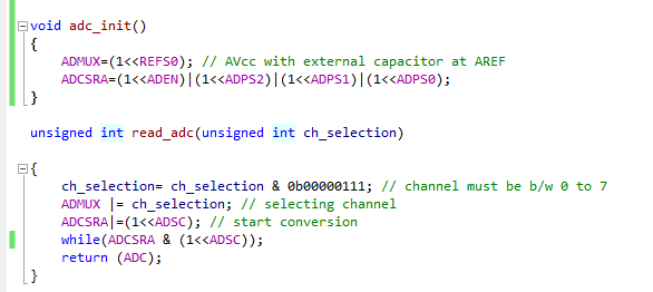
Bit 7 used to ADC ON (ADC Turn ONing by applying a high bit )
Bit6 ADSC is used to start the conversion .and still maintain it value as high up to the conversion . after conversion it becomes low (Zero)
ADATE and ADIF is not used by me now .(not by using Intruppet
Bit 0 to bit2 is used for select ADC frequency .
\
2) ADC: It is a 16 bit to 8 bit register ADCL & ADCH. By applying right shift value it is autmatically set as normal value so we can take simple value from it
eg : return (ADC);
adc_value = read_adc(ch_sec);
The program as follows . The full program can be download below including Proteus simulation file.
#define F_CPU 12000000UL #include <avr/io.h> #include<util/delay.h> #define LCDPORT PORTD // Renaming the PORTD to LCDPORT #define RS PD2 // Renaming the RS pin to 2 #define E PD3 // Renaming the E to number 3 #define LINE2 lcd_cmd(0xc0); void latch(void) // used to a high to low pulse the pin E { PORTD |= ~(1<<E); // here we give a high to PORTD.3 _delay_ms(1); PORTD |= (1<<E); // Here we give a LOW to PORTD.# }
void lcd_cmd(unsignedchar c) // used to send the command / Instruction to the lcd port { PORTD |= ~(1<<RS); // send a '0' value to select to send command _delay_ms(1); LCDPORT = c & 0xf0; // send the command c only 4 bit by masking the lower bit latch(); _delay_ms(1); LCDPORT = (c << 4); // giving the lowerbit by shifting the 4 bit to left latch(); }
void lcd_data(unsignedchar c) { PORTD |= (1<<RS); // send 1 to send data _delay_ms(1); LCDPORT = c & 0xf0| 0x4; //send the data only 4 bit by masking the lower bit and also making the RS pin high by giving 0x04 . _delay_ms(1); latch();
LCDPORT = (c << 4)| 0x4; ; // giving the lower bit by shifting the 4 bit to left latch(); }
void lcd_init() { _delay_ms(20); lcd_cmd(0x30); //as per data sheet _delay_ms(20); lcd_cmd(0x30); //as per data sheet _delay_ms(4); lcd_cmd(0x32); //as per data sheet _delay_ms(4); lcd_cmd(0x28); // Function set (4-bit interface, 2 lines, 5*7Pixels) lcd_cmd(0x28); // Function set (4-bit interface, 2 lines, 5*7Pixels) lcd_cmd(0x0c); // Make cursorinvisible lcd_cmd(0x6); // Set entry Mode(auto increment of cursor) }
voidstring(constchar *q) // used to send single charcter to display the lcd { while (*q) { lcd_data(*q++); } }