-->
Showing posts with label Interfacing. Show all posts

Transformer Configuration in Proteus

By

Setting up A Transformer in Proteus


The calculation Formula is  L1/L2 = (V1/V2)^2

For Example: Design for 6 Volt input ,230volt 50Hz Not considered wattage just for simulation. 

           Assign L1 = 1H (but 1henry expectable for a 10 or 20 kW transformer)

        Then L2 = 1/(230/6)^2
                       = 680.5293micro Henry


Design of Digital Voltmeter By using Microcontroller

By
Tutorial for Atmeag8 /AVR based Voltmeter

               It measures the Ac voltage and shows readings in RMS value.

Basics Of AC signal 

The AC signal ,its amplitude varying in accordance with time. In india AC frequency is 50Hz.

Then the Time period one full cycle ,
        
  T = 1/frequency 
  T = 1/50Hz = .002second 
                     = 20milli Second
                     = 10 Milli second for Half Cycle


There are a lot of methods for measuring AC volt digitally

we could find the RMS value by multipliying the Peak Voltage with 0.707. 

   Vrms = Peak Voltage * 0.707 .

Approximatly Indian Line AC Peak volatge is 325v.

  Example : 
                 325v *0.707 = 229.775Volt      .(appro = 230Vrms).

But Microcontroller could only sense  up to 5 volt  as well as it couldnt sense negative values

so we cannot  give 230 volt directly to It .
It can be rectify by using a Stepdown transformer ,which has an advantage of safety.
Ac voltage can be reduce by using transformer to comfortable range . (ie 0 to 5volt DC)

make the calculation  as   ,
 The voltage Divider would give a 5 volt when the Vrms 230v. [will be more give details on the way ].


The full wave rectifier output will give to ADC of micro controller . Then do corresponding coding.

Microcontroller Section 
I am using here Amega8. 
we need to mesure only one half cycles repeatedly because  the waves same are repeating 
Basics

I selected , the F_cpu frequency is the internal RC Oscillator 8MHz.
Atmega8 ADC uses Prescalar [frequency reducer or divider by 2th,4th etc]
Atmega ADC  Prescale Frequency is in between 50Khz to 200Kz
ADC conversion time is in between 13 to 260 micro second.

ADC frequency = F_cpu / Prescaler

                         = 800,000HZ  / 8
  
                        = 62.5KHz

At high frequency ADC conversion would be fast while at lower frequency the conversion will be more accuracy.

ADC conversion time Calculation 

Conversion Time = 1/ADC frequency

                           = 1/62500 
                           = 0.000016 Second
                           = 0.016 Milli Second
                           = 16 Micro Second.     [At 62.500KHz]

So 16 mirco second would taken for one cycle of  conversion.with 62,5KHz.

13 ADC cycles required for one conversion

ie,
    13 * 16Micro Second = 230 Micro Second [approximately]
                                      = 230us.

The Half wave has 10milli second time duration.[100000microsecond].

There the available conversion times is 

                                        =  Total time period for a half cycle /one ADC conversion time  
                                        
                                        = 10000 micro second / 230 micro second
                 
                                        = 43.4 samples  [ for one half cycleie 10 milli second]

                                       
    Image Shows only 7 Samples per half cycles .in our case it is 43

And again reduced the sampling to 40 .

calculation of Vpeak

 Takes the largest Vpeak from the 40 samples.
Vrms = Vpeak * .707
*****************************************************************************

Atmega8 ADC StepSize Calculation

The Atmega8 ADC is a 10 Bit /[ie the Maximum high value is 1023 =1111111111] at which the ADC will give fullscale Value .
The ADC  require a clock as well as a reference voltage .
The resolution of ADC output decide the Step size.

ADC o/p = Vin * 1024 / Vref

Examples;
  Vin =5volt , Vref =5volt 

                 ADC o/p = 5 * 1023 /5 = 1023 [ADC highest Value]

               Step Size  voltage = Vref / 1023 = 0.004887 volt =4.88millivolt
             One binary digit changes when 4.88volt changes takes place


Image's Step Size is 1.25 volt


*******************************************************************************************************

Atmega-based-Menu-building-lcd-16x2

By

A menu system Applicable for various microcntroller projects ,Not fully completed only for learning the full code and proteus are available below to download for learning purpose thanking you 

/*
* push_button__lcdMenu.c
*
* Created: 7/30/2017 11:48:27 AM
* Author: Krishna
*/

#include
#include "lcd.h"
#include "delay.h"
#include "button_key.h"
# define F_CPU 1000000UL


struct menu s1= {0}; //s1.menu_up-key =1;


int main(void)
{ int a;
struct menu s1= {0}; //s1.menu_up-key =1;
const char *menu_display[10];
menu_display[0] = " Select Menu";
menu_display[1] = " Set Time";
menu_display[2] = " Set Date";
menu_display[3] = " Set Alaram";
menu_display[4] = " Set Alaram ";
//sub menu
menu_display[5] = " Enter Time ";
menu_display[6] = " Enter Date ";
menu_display[7] = " Enter Alarm ";
menu_display[8] = " Enter Alarm";
LCD_SetUp(PB_0,PB_1,PB_2,P_NC,P_NC,P_NC,P_NC,PB_4,PB_5,PB_6,PB_7);
LCD_Init(2,16);
LCD_GoToLine(0);

DELAY_ms(100);
//LCD_Clear();
while(1)
{

// key_display( key_value);
menu_key_display (s1,menu_display);


LCD_Clear();
for(a=0; a<5 a="" d="" lcd_printf="" pre="" s1.time="">
/*
* button_key.c
*
* Created: 7/30/2017 12:02:39 PM
* Author: Krishna
*/ #include
#include "delay.h"
#include "button_key.h"
#include "lcd.h"

void menu_key_display(struct menu s1,const char *menu_display[]);
void UP_Down_Keyvalue(struct menu s1,int i,int j);

/* Function Key Value For get key */
int Key_pressed(void)
{
while(1){
if (LEFT_S) { while(LEFT_S);return 1; }
if (RIGHT_S){ while(RIGHT_S);return 2; }
if (UP_S) { while(UP_S); return 3; }
if (DOWN_S) { while(DOWN_S);return 4 ; }
if (OK_S) { while(OK_S);return 5 ; }
}
}


/* Function Key Value For Up Key & Enter*/

void menu_key_display(struct menu s1,const char *menu_display[])
{
int ch;
int a;
int menu_position =0;
LCD_DisplayString(menu_display[menu_position]);
do{

repat:
ch = Key_pressed();
if(ch==1||ch==2)
{
if(ch==2)
{ if(ch==2)
{ if(s1.menu_side_key==4)
s1.menu_side_key = 0;
LCD_Clear();
LCD_GoToLine(0);
LCD_DisplayString(*((++s1.menu_side_key)+menu_display));
menu_position=1;

}
}
else if(ch==1)
{
if(ch==1)
{if(s1.menu_side_key==1 ||s1.menu_side_key==0)
{
s1.menu_side_key=5;
}
LCD_Clear();
LCD_DisplayString(*((--s1.menu_side_key)+menu_display));
menu_position=1;
}
}
}

if(menu_position==0)
goto repat;
}while(ch!=5);

a = s1.menu_side_key;
switch(a)
{
case 1: // set time
{
LCD_Clear();
LCD_GoToLine(0);
LCD_DisplayString(menu_display[5]);
LCD_GoToLine(1);
LCD_DisplayString(" HH:MM:SS:PM/AM");
UP_Down_Keyvalue(s1,2,4);
break;
}
case 2: // Set date
{
LCD_Clear();
LCD_GoToLine(0);
LCD_DisplayString(menu_display[6]);
LCD_GoToLine(1);
LCD_DisplayString(" DD:MM:YY");
UP_Down_Keyvalue(s1,2,3);
break;
}

case 3: // set alarm
{
LCD_Clear();
LCD_GoToLine(0);
LCD_DisplayString(menu_display[7]);
LCD_GoToLine(1);
LCD_DisplayString(" HH:MM:SS:AM/PM");
UP_Down_Keyvalue(s1,2,4);
break;
}
case 4: // set alarm
{
LCD_Clear();
LCD_GoToLine(0);
LCD_DisplayString(menu_display[8]);
LCD_GoToLine(1);
LCD_DisplayString(" HH:MM:SS:PM/AM");
UP_Down_Keyvalue(s1,2,4);
break;
}
}

while(Key_pressed()!=5);


}


/* Function Key Value For UP_Down Key */
void UP_Down_Keyvalue(struct menu s1,int i,int j)
{

int ch,lower,upper;
do{
if(j==4)
{
if(i==2)upper=1;
if(i==3)upper=9;
if(i==5)upper=5;
if(i==8)upper =5;
if(i==9)upper =9;
}
if(UP_S)
{
while(UP_S);
if(s1.menu_up_key==upper)
s1.menu_up_key = lower-1;
LCD_GoToXY(1,i);
LCD_Printf("%d",++s1.menu_up_key);
s1.time[i-2]=s1.menu_up_key;
}
else if(DOWN_S) // down

{ while(DOWN_S);
if (s1.menu_up_key==lower)
s1.menu_up_key = upper+1;
LCD_GoToXY(1,i);
LCD_Printf("%d",--s1.menu_up_key);
s1.time[i-2]=s1.menu_up_key;
}
if(RIGHT_S)

{ while(RIGHT_S);
s1.menu_up_key=0;
if(i==9) goto exit1;
if(i==3||i==6)
++i;
i++;
}
exit1:
if (LEFT_S)
{ while(LEFT_S);
s1.menu_up_key=0;
if(i==2) goto exit2;
if(i==5||i==8)
--i;
i--;

}
exit2:continue;


} while (ch!=5); // if Okay key exit loop

}


https://youtu.be/bNwrHuY4Kxk

Atmega-based-Menu-building-lcd-16x2

By

A menu system Applicable for various microcntroller projects ,Not fully completed only for learning the full code and proteus are available below to download for learning purpose thanking you 

/*
 * push_button__lcdMenu.c
 *
 * Created: 7/30/2017 11:48:27 AM
 *  Author: Krishna
 */ 

#include 
#include "lcd.h"
#include "delay.h"
#include "button_key.h"
# define F_CPU 1000000UL


struct menu s1= {0}; //s1.menu_up-key =1;


int main(void)
{   int a;
 struct menu s1= {0}; //s1.menu_up-key =1;
 const char *menu_display[10];
 menu_display[0] = "   Select Menu";
 menu_display[1] = "  Set Time";
 menu_display[2] = "  Set Date";
 menu_display[3] = "  Set Alaram";
 menu_display[4] = "  Set Alaram ";
 //sub menu
 menu_display[5] = "  Enter Time ";
 menu_display[6] = "  Enter Date ";
 menu_display[7] = "  Enter Alarm ";
 menu_display[8] = "  Enter Alarm";
    LCD_SetUp(PB_0,PB_1,PB_2,P_NC,P_NC,P_NC,P_NC,PB_4,PB_5,PB_6,PB_7);
    LCD_Init(2,16);
    LCD_GoToLine(0);
   
    DELAY_ms(100);
 //LCD_Clear();  
  while(1)
 {
     
  // key_display( key_value); 
   menu_key_display (s1,menu_display);
   
  
   LCD_Clear();
   for(a=0; a<5 a="" d="" lcd_printf="" pre="" s1.time="">
/*
 * button_key.c
 *
 * Created: 7/30/2017 12:02:39 PM
 *  Author: Krishna
 */ #include 
 #include "delay.h"
  #include "button_key.h"
  #include "lcd.h"  
    
void menu_key_display(struct menu s1,const char *menu_display[]);
void UP_Down_Keyvalue(struct menu s1,int i,int j);

 /* Function Key Value For get key  */
int Key_pressed(void)
 { 
 while(1){
    if (LEFT_S) {  while(LEFT_S);return 1; }      
 if (RIGHT_S){  while(RIGHT_S);return 2; }
 if (UP_S)  {  while(UP_S); return 3; }
 if (DOWN_S) { while(DOWN_S);return 4 ; }
 if (OK_S) { while(OK_S);return 5 ; }
 } 
 } 
 
 
 /* Function Key Value For Up Key  & Enter*/
 
 void menu_key_display(struct menu s1,const char *menu_display[])
 {   
  int ch; 
   int a; 
  int  menu_position =0;
   LCD_DisplayString(menu_display[menu_position]);
            do{  
    
    repat:          
    ch = Key_pressed();
    if(ch==1||ch==2)
    {
                  if(ch==2)
                    {  if(ch==2)
                   { if(s1.menu_side_key==4)
                     s1.menu_side_key = 0;
                  LCD_Clear();
                  LCD_GoToLine(0);
                              LCD_DisplayString(*((++s1.menu_side_key)+menu_display)); 
         menu_position=1;            
         
                 } 
                      }
                   else if(ch==1)
                   {   
                             if(ch==1)
                    {if(s1.menu_side_key==1 ||s1.menu_side_key==0)
                      {
                    s1.menu_side_key=5;
                      }
                      LCD_Clear();
                            LCD_DisplayString(*((--s1.menu_side_key)+menu_display));                            
          menu_position=1;   
                         }
                   }  
          }
      
    if(menu_position==0)
    goto repat;
        }while(ch!=5);
       
        a = s1.menu_side_key; 
  switch(a)
     { 
 case 1: // set time
          { 
    LCD_Clear();
       LCD_GoToLine(0);
       LCD_DisplayString(menu_display[5]);
    LCD_GoToLine(1);
    LCD_DisplayString("  HH:MM:SS:PM/AM");
    UP_Down_Keyvalue(s1,2,4);    
          break;
          } 
 case 2: // Set date
        {
         LCD_Clear();
         LCD_GoToLine(0);
         LCD_DisplayString(menu_display[6]);
      LCD_GoToLine(1);
      LCD_DisplayString("  DD:MM:YY");
      UP_Down_Keyvalue(s1,2,3);     
         break;
        }
 
 case 3: // set alarm
          {
         LCD_Clear();
            LCD_GoToLine(0);
         LCD_DisplayString(menu_display[7]);
      LCD_GoToLine(1);
      LCD_DisplayString(" HH:MM:SS:AM/PM");
      UP_Down_Keyvalue(s1,2,4);      
          break;
             }
 case 4:  // set alarm
           {
            LCD_Clear();
          LCD_GoToLine(0);
          LCD_DisplayString(menu_display[8]);
    LCD_GoToLine(1);
    LCD_DisplayString("  HH:MM:SS:PM/AM");
    UP_Down_Keyvalue(s1,2,4);    
          break;
            }
     } 
    
  while(Key_pressed()!=5); 
  
       
 } 


 /* Function Key Value For UP_Down Key */
 void UP_Down_Keyvalue(struct menu s1,int i,int j)
 {    
  
  int ch,lower,upper;    
  do{  
    if(j==4)
     {
      if(i==2)upper=1;
      if(i==3)upper=9;
      if(i==5)upper=5;
      if(i==8)upper =5;
      if(i==9)upper =9;
     } 
      if(UP_S)   
      {
      while(UP_S);    
      if(s1.menu_up_key==upper)
      s1.menu_up_key = lower-1;
      LCD_GoToXY(1,i); 
      LCD_Printf("%d",++s1.menu_up_key);
      s1.time[i-2]=s1.menu_up_key;          
      }
   else if(DOWN_S) // down 
             
          {    while(DOWN_S);
            if (s1.menu_up_key==lower)
            s1.menu_up_key = upper+1;        
            LCD_GoToXY(1,i);
            LCD_Printf("%d",--s1.menu_up_key);
      s1.time[i-2]=s1.menu_up_key;       
     }
          if(RIGHT_S)
       
             { while(RIGHT_S);
       s1.menu_up_key=0;
          if(i==9) goto exit1;
          if(i==3||i==6)
          ++i;
          i++;
              }
      exit1:
           if (LEFT_S)
             { while(LEFT_S);
        s1.menu_up_key=0;
            if(i==2) goto exit2;         
            if(i==5||i==8)
            --i;
            i--;
     
             }
    exit2:continue;
   
   
  } while (ch!=5);  // if Okay key exit loop
  
 }


https://youtu.be/bNwrHuY4Kxk

Making multiple input by 3 wire Interfacing .

By
Parallel to serial  Interfacing with Micro controller 

Interfacing with 74HC165 with 8051


   I am trying to make multiple input with using minimum input port of micro controller ,ie 3 wire .
By using a 3 wire we can interface more input as we wish.


 I am making a tutorial for it , Basics of 74HC165  which is a parallel to serial shift register .


Only three pin is connected with this IC . 
1)   SH/LD  or PL  is used load  parallel data to the IC .A low pulse (ground) is applied for store the         parallel data at the pin from A to H . And a High (5 Volt) is applied to stop the reading from the          PIN A to H .
2) Then to read the loaded or saved data to Micro controller we have to give clock to the PIN 2 of           74HC165  (CLK) . 8 pulses is applied to read 8 bit (Pin A to B)

3) QH / SO . serial out pin is used to get the stored parallel data to serially.

The CLK INH pin must be connect in ground for enable clock.


    To use cascaded 74HC165 for increasing i/p .connect the Seriall output pin (PIN 9) of first satge into serial input of first stage see the following circuit.


see the code below


  #include  
#include
#include "lcd.h"
sbit PL = P1^0; // Loading parallel data to HC165.
sbit CLK = P1^1; // Clock pulse to HC165.
sbit Beep = P1^2; //
sbit data_in = P1^3;

void clock(void);
void display(unsigned char value);

void main()
{
unsigned char position ,no_of_ip = 17;
lcd_init();
string(" gElectron");
while(1)

{
PL = 0 ;
delay(2);
PL = 1;

for(position = 1; no_of_ip > position; position++ , clock())
{

if(data_in == 1)
display(position);

}
}
}

void clock(void)
{
CLK = 1;
delay(1);
CLK = 0;

}

void display(unsigned int value)
{
unsigned int a[1];
Beep = 1;
lcd_init();
lcd_cmd(0x01);
string("Pressed key ");
lcd_cmd(0xc0);
sprintf(a,"%d",value);
string(a);
delay(1);
Beep = 0;

}

Download the whle file here github.

Making multiple input by 3 wire Interfacing .

By
Parallel to serial  Interfacing with Micro controller 

Interfacing with 74HC165 with 8051


   I am trying to make multiple input with using minimum input port of micro controller ,ie 3 wire .
By using a 3 wire we can interface more input as we wish.


 I am making a tutorial for it , Basics of 74HC165  which is a parallel to serial shift register .


Only three pin is connected with this IC . 
1)   SH/LD  or PL  is used load  parallel data to the IC .A low pulse (ground) is applied for store the         parallel data at the pin from A to H . And a High (5 Volt) is applied to stop the reading from the          PIN A to H .
2) Then to read the loaded or saved data to Micro controller we have to give clock to the PIN 2 of           74HC165  (CLK) . 8 pulses is applied to read 8 bit (Pin A to B)

3) QH / SO . serial out pin is used to get the stored parallel data to serially.

The CLK INH pin must be connect in ground for enable clock.


    To use cascaded 74HC165 for increasing i/p .connect the Seriall output pin (PIN 9) of first satge into serial input of first stage see the following circuit.


see the code below


  #include  
#include
#include "lcd.h"  
sbit PL  = P1^0;   // Loading parallel data to HC165.
sbit CLK = P1^1;   // Clock pulse to HC165.
sbit Beep  = P1^2;   // 
sbit data_in  = P1^3;

  void clock(void);
  void display(unsigned char value);
     
void main()
{  
 unsigned char position ,no_of_ip = 17;
  lcd_init();
  string("   gElectron");     
  while(1)

   {  
      PL = 0 ;
  delay(2);
  PL = 1;

   for(position = 1; no_of_ip > position; position++ , clock())
  {     
  
    if(data_in == 1)
     display(position);   

  }
   } 
}  

 void clock(void)
 {
   CLK = 1;
   delay(1);
   CLK = 0;

 }

void display(unsigned int value)
  {  
  unsigned int a[1];
    Beep =   1;
    lcd_init();
 lcd_cmd(0x01);   
    string("Pressed key ");
    lcd_cmd(0xc0); 
  sprintf(a,"%d",value);  
     string(a); 
     delay(1);
     Beep = 0;
     
  }   


Download the whle file here github.

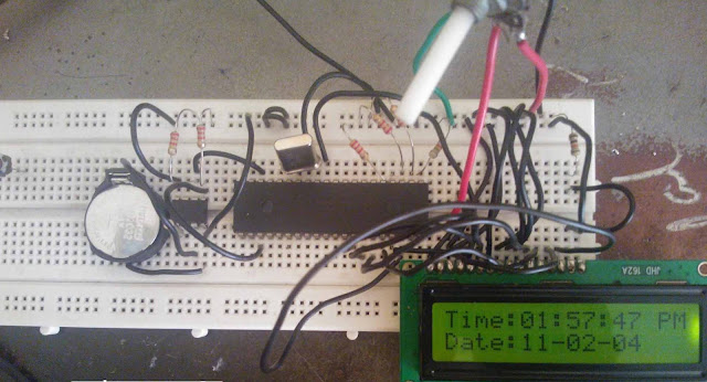
DS1307_Tutorials

By
   The real time clock chip, DS1307, can be connected to the Arduino and used in a wide range of projects that require the processor to know the time and date.  Using this device is easy if you have a basic understanding of the Wire.h library functions and I2C communication protocol.  In this document we will discuss the basic operation of the device, how to set the date and time and how to read the information.  This document also includes several Arduino programs that can be referenced to get started with the RTC.
[ads-post]


RTC overview
The DS1307 chip is a simple device integrated circuit that counts clock pulses.  The chip requires a 32.768 kHz oscillator commonly known as a watch crystal.  You will remember the binary number 0x7FFF is 32768. This means that a 15 bit counter would count from 0 up to its maximum value an role over to 0 again in exactly 1 second, if clocked at this frequency.  The chip includes a built in processor which includes the counter and several registers that keep track of the day, the date and the time.  The device also has additional memory for storage.

The design is intended to use very little power, less than 0.5µA and it runs on 5 volts, but if the supply voltage drops to 3, the oscillator will continue to operate and keep accurate time.  The device is intended to have a CR1220 back up battery to support continued operation when the power has been unplugged.

The DS1307 interfaces with the outside world using the I2C protocol, making it easy to program and read with the Arduino I2C internal peripheral.  The Arduino I2C port uses analog pin A4 and A5 as the data and clock lines.  The Arduino TwoWire class is loaded with the Wire.h include which activates the I2C peripheral and includes the routines that are used in this product description.


RTC registers
Registers are 8 bit (1 byte) memory locations that can store values. The RTC uses the I2C interface to write and read bytes from these registers.  The DS1307 has 0x37 (64) of these registers, however only the first 8 are important to the operation of the device.

Understanding and using BCD and ASCII
The register data is stored in BCD (Binary Coded Decimal) format.  This means that each digit of a number is given 4 bytes (1 nibble).  Each of these nibbles is allowed to use values 0 to 9 or 0000 to 1001.  This means that when we write a number in hex, we can read the number as a decimal number.

The BCD number 0011 0100 is understood to be 34 in decimal. BCD is seldom used, but this device make use of it.  To format the data correctly one must make use of the ">>" shift right and "<<" shift left operators to create numbers that will properly represent the information.  Also, it is necessary to be familiar with AND "&" and the OR "|" functions.  In addition, it is often more useful to think in of numbers in terms of hex and binary than in decimal.

Consider the first register which contains the current seconds.  Suppose the current time is 7:44:26 - 7 AM, 44 minutes and 26 seconds.  To set this time correctly, the appropriate values must be written to the correct registers.  Register 00 contains the seconds value.  It needs to set to be the binary number 0010 0110 or hex 0x26.  The program must convert the decimal number 26 into the hex number 0x26.

Bit Manipulations in Hours
We can immediately write the minutes and seconds numbers to the registers.  The hour byte needs a little work.  From the data sheet for the DS1307 we read "The DS1307 can be run in either 12-hour or 24-hour mode. Bit 6 of the hours register is defined as the 12-hour or 24-hour mode-select bit. When high, the 12-hour mode is selected. In the 12-hour mode, bit 5 is the AM/PM bit with logic high being PM. In the 24-hour mode, bit 5 is the second 10-hour bit (20 to 23 hours). The hours value must be re-entered whenever the 12/24-hour mode bit is changed."

If we want to be in 12 hour mode, bit we need to set bits 5 and 6 - 5 specifies AM or PM - 6 defines the mode and must be 1 if we are in 12 hour mode.  5 must be set if we are entering a PM hour.  In 24 hour mode 6 is 0, and 5 is already either 0 or 1 if the hour is greater than 19.  That means we are already set to do 24 hour mode, but if we wish to change to 12 hour mode, we need to make some changes.

We need to change the way data is entered - that's simple enough, but we also need to know how to set or clear bits.  To do this we must understand some simple bit manipulation routines.  We can use the bitSet(Nmbr, bit) and bitClear(Nmbr, bit) functions that are built into the Arduino IDE.  However, this is an excellent opportunity to explore some new and very interesting bit manipulations.

First the AND and OR functions. When we want to AND two numbers we use the "&" symbol.  The OR function uses "|".  When we AND two numbers together, each bit in the first number is anded with the same bit in the second number - The rule is:
   1 & 1 = 1, 1 & 0 = 0, 0 & 0 = 0, 0 & 1 = 0.

Consider the two binary numbers B011011001 & B01101011 = B011010001.  Notice how when there is a 0 in either number the result has a 0 in that place - to get a 1 you must have a 1 in that place in the first number AND the second number.

The OR function follows a different rule:
1 & 1 = 1, 1 & 0 = 1, 0 & 0 = 0, 0 & 1 = 1.

In this case a 1 in either the first number OR the second number will give a 1 as a result.

B011011001 | B01101011 = B011011011

To turn on a particular bit in a number, we use a "mask".  This is a particular binary string that is all 0s except for a 1 in the place where we want to change make sure there is a 1 in the answer.  In our problem, we want to turn on bit 6 in the hour register to set the operation to 12 hour mode.

We would use the mask B01000000.  This number OR with Hrs will give us a number that has a 1 in the 12/24 select bit.  Note the "B" in front of the binary number - The easiest way to define a mask is to write it in Binary.  Just as "0x" in front of a hex number will tell the compiler the digit that follow are hex digits, the "B" in front of a series of 1s and 0s will tell the compiler that what follows is binary.

Hrs | B01000000 would give us the correct result. A 0 in the mask leaves the Hrs unchanged, but a 1 forces the result to have a 1 in that position.

To turn this bit off, we could use an and mask B10111111 an AND this with Hrs to put us in 24 hour mode.

Hrs & B10111111.  A "1" in the mask leaves the Hrs unchanged, but a 0 forces the result to have a 0 in that position.

*********************************************************************************

Most of the people doubts about How to select the Hour in 12 or 24 mode , giving a sample example as follows

Hours = 0x40 | Hours;  
Just masking with 0x40

Thats it ,Here the 6 the bit position set as High so RTC selected 12 Hours mode

More details from here
http://www.edaboard.com/thread341519.html

DS1307_Tutorials

By
   The real time clock chip, DS1307, can be connected to the Arduino and used in a wide range of projects that require the processor to know the time and date.  Using this device is easy if you have a basic understanding of the Wire.h library functions and I2C communication protocol.  In this document we will discuss the basic operation of the device, how to set the date and time and how to read the information.  This document also includes several Arduino programs that can be referenced to get started with the RTC.
[ads-post]


RTC overview
The DS1307 chip is a simple device integrated circuit that counts clock pulses.  The chip requires a 32.768 kHz oscillator commonly known as a watch crystal.  You will remember the binary number 0x7FFF is 32768. This means that a 15 bit counter would count from 0 up to its maximum value an role over to 0 again in exactly 1 second, if clocked at this frequency.  The chip includes a built in processor which includes the counter and several registers that keep track of the day, the date and the time.  The device also has additional memory for storage.

The design is intended to use very little power, less than 0.5µA and it runs on 5 volts, but if the supply voltage drops to 3, the oscillator will continue to operate and keep accurate time.  The device is intended to have a CR1220 back up battery to support continued operation when the power has been unplugged.

The DS1307 interfaces with the outside world using the I2C protocol, making it easy to program and read with the Arduino I2C internal peripheral.  The Arduino I2C port uses analog pin A4 and A5 as the data and clock lines.  The Arduino TwoWire class is loaded with the Wire.h include which activates the I2C peripheral and includes the routines that are used in this product description.


RTC registers
Registers are 8 bit (1 byte) memory locations that can store values. The RTC uses the I2C interface to write and read bytes from these registers.  The DS1307 has 0x37 (64) of these registers, however only the first 8 are important to the operation of the device.

Understanding and using BCD and ASCII
The register data is stored in BCD (Binary Coded Decimal) format.  This means that each digit of a number is given 4 bytes (1 nibble).  Each of these nibbles is allowed to use values 0 to 9 or 0000 to 1001.  This means that when we write a number in hex, we can read the number as a decimal number.

The BCD number 0011 0100 is understood to be 34 in decimal. BCD is seldom used, but this device make use of it.  To format the data correctly one must make use of the ">>" shift right and "<<" shift left operators to create numbers that will properly represent the information.  Also, it is necessary to be familiar with AND "&" and the OR "|" functions.  In addition, it is often more useful to think in of numbers in terms of hex and binary than in decimal.

Consider the first register which contains the current seconds.  Suppose the current time is 7:44:26 - 7 AM, 44 minutes and 26 seconds.  To set this time correctly, the appropriate values must be written to the correct registers.  Register 00 contains the seconds value.  It needs to set to be the binary number 0010 0110 or hex 0x26.  The program must convert the decimal number 26 into the hex number 0x26.

Bit Manipulations in Hours
We can immediately write the minutes and seconds numbers to the registers.  The hour byte needs a little work.  From the data sheet for the DS1307 we read "The DS1307 can be run in either 12-hour or 24-hour mode. Bit 6 of the hours register is defined as the 12-hour or 24-hour mode-select bit. When high, the 12-hour mode is selected. In the 12-hour mode, bit 5 is the AM/PM bit with logic high being PM. In the 24-hour mode, bit 5 is the second 10-hour bit (20 to 23 hours). The hours value must be re-entered whenever the 12/24-hour mode bit is changed."

If we want to be in 12 hour mode, bit we need to set bits 5 and 6 - 5 specifies AM or PM - 6 defines the mode and must be 1 if we are in 12 hour mode.  5 must be set if we are entering a PM hour.  In 24 hour mode 6 is 0, and 5 is already either 0 or 1 if the hour is greater than 19.  That means we are already set to do 24 hour mode, but if we wish to change to 12 hour mode, we need to make some changes.

We need to change the way data is entered - that's simple enough, but we also need to know how to set or clear bits.  To do this we must understand some simple bit manipulation routines.  We can use the bitSet(Nmbr, bit) and bitClear(Nmbr, bit) functions that are built into the Arduino IDE.  However, this is an excellent opportunity to explore some new and very interesting bit manipulations.

First the AND and OR functions. When we want to AND two numbers we use the "&" symbol.  The OR function uses "|".  When we AND two numbers together, each bit in the first number is anded with the same bit in the second number - The rule is:
   1 & 1 = 1, 1 & 0 = 0, 0 & 0 = 0, 0 & 1 = 0.

Consider the two binary numbers B011011001 & B01101011 = B011010001.  Notice how when there is a 0 in either number the result has a 0 in that place - to get a 1 you must have a 1 in that place in the first number AND the second number.

The OR function follows a different rule:
1 & 1 = 1, 1 & 0 = 1, 0 & 0 = 0, 0 & 1 = 1.

In this case a 1 in either the first number OR the second number will give a 1 as a result.

B011011001 | B01101011 = B011011011

To turn on a particular bit in a number, we use a "mask".  This is a particular binary string that is all 0s except for a 1 in the place where we want to change make sure there is a 1 in the answer.  In our problem, we want to turn on bit 6 in the hour register to set the operation to 12 hour mode.

We would use the mask B01000000.  This number OR with Hrs will give us a number that has a 1 in the 12/24 select bit.  Note the "B" in front of the binary number - The easiest way to define a mask is to write it in Binary.  Just as "0x" in front of a hex number will tell the compiler the digit that follow are hex digits, the "B" in front of a series of 1s and 0s will tell the compiler that what follows is binary.

Hrs | B01000000 would give us the correct result. A 0 in the mask leaves the Hrs unchanged, but a 1 forces the result to have a 1 in that position.

To turn this bit off, we could use an and mask B10111111 an AND this with Hrs to put us in 24 hour mode.

Hrs & B10111111.  A "1" in the mask leaves the Hrs unchanged, but a 0 forces the result to have a 0 in that position.

*********************************************************************************

Most of the people doubts about How to select the Hour in 12 or 24 mode , giving a sample example as follows

Hours = 0x40 | Hours;  
Just masking with 0x40

Thats it ,Here the 6 the bit position set as High so RTC selected 12 Hours mode

More details from here
http://www.edaboard.com/thread341519.html

More Posts

gElectron. Powered by Blogger.

Contributors

16x2 LCD Interfacing with STM32,STM32F103C6

 16x2 LCD  Interfacing with STM32,STM32F103C6 lcd_init(); LCD_LINE1; lcd_String(" GeElectron"); LCD_LINE2; lc...

Contact Form

Name

Email *

Message *

Contact us

Name

Email *

Message *

Follow Us

https://www.facebook.com/gElectron-393939667321867/ FBbox/https://www.facebook.com/IVYthemes

Comments

[blogger]

MKRdezign

Test

Latest

[recent][newsticker]

Technology

Top Ads

RECENT COMMENTS

Subscribe Via Email

Subscribe to our newsletter to get the latest updates to your inbox. ;-)


Your email address is safe with us!

RECENT COMMENTS