
.......LCD Interfacing.......
..........................................................
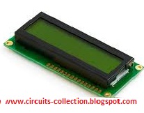
LCD display is commonly used in most of the micro controller based projects. A different kind of LCD modules are available in the market. The display used here is 16X2 LCD it meas that 16 character per line by 2 lines.Hitachi HD 44780 LCD controller is one of the most common dot matrix Liquid Cristal Display controller available in the market (4more).
Datasheet of Hitachi HD 44780 LCD controller Download here.


The 44780 standard has 16 pins 8 pins for data or instruction .
The 44780 standard requires 3 control lines as well as either 4 or 8 I/O lines for the data bus.
ie , it can interface with 3 control line + 4 I/O -----> called 4 bit mode

The Lcd works according to the data comes from the micro controller. We gives the data from micro-controller to the LCD port of the DB0 - DB7 (see the picture) these applying data is 8 bit data ,because ,Hitachi HD 44780 LCD controller has two 8 bit registers named an instruction register (IR) and a data register (DR).we can disscuss later about the instruction register and data register .
3 Control Lines RS,RW and EN -Pin No: 4,5,6 respectively.
RS-is the "Register select " the 8 bit data gives to the LCD from the micro-controller are of two type one is the command data (these command data are giving to the LCD's internal controller and the controller decide as display screen ,position,clear disply ,second line etc according to the command data ) ,which is 8 bit .
Datasheet of Hitachi HD 44780 LCD controller Download here.
The 44780 standard has 16 pins 8 pins for data or instruction .
The 44780 standard requires 3 control lines as well as either 4 or 8 I/O lines for the data bus.
ie , it can interface with 3 control line + 4 I/O -----> called 4 bit mode
or , it can interface with 3 control lines + 8 I/O -----> called 8 bit mode

The Lcd works according to the data comes from the micro controller. We gives the data from micro-controller to the LCD port of the DB0 - DB7 (see the picture) these applying data is 8 bit data ,because ,Hitachi HD 44780 LCD controller has two 8 bit registers named an instruction register (IR) and a data register (DR).we can disscuss later about the instruction register and data register .
3 Control Lines RS,RW and EN -Pin No: 4,5,6 respectively.
RS-is the "Register select " the 8 bit data gives to the LCD from the micro-controller are of two type one is the command data (these command data are giving to the LCD's internal controller and the controller decide as display screen ,position,clear disply ,second line etc according to the command data ) ,which is 8 bit .
And the second data is the data which is actually display to LCD (string,name ,numbers etc)
When RS is low (0) the data coming from the micro-controller to the LCD data port is treated as command data
For example
8 bit controller out put port is named as P0 (8 bit )
RS = 0; // select the register in command mode
P0 = 0x20 // giving a 8 bit data work the LCD as 4-bit, 1 Line, 5x7 Dots refer above command
When RS is high (1) ,the data coming from the micro-controller to the LCD data port is the text data which should be displayed on the screen.
For example, to display the letter "m" on the screen you would set RS high.
RS = 1; // select the register in Data mode
P0 = 0x20 // giving a 8 bit data,that will be displayed on the LCD screen.
RW :- When RW is low(0), the data from the micro-controller is being written to the LCD. When RW is high (1), the microcontroller reads the data from the LCD (eg: busy flag testing )
Most of the times there is no need to read the LCD so this(RW) lines can be connected to ground directly,for saving controller one I/O port line.
EN :- line is called "Enable." This control line is used to tell the LCD that you are sending it data. To send data to the LCD, your program should make sure this line is low (0) and then set the other two control lines and/or put data on the data bus. When the other lines are completely ready, bring EN high (1) and wait for the minimum amount of time required by the LCD datasheet (this varies from LCD to LCD), and end by bringing it low (0) again.
Some LCD Basic Commands:
No.
|
Instruction
|
Hex
|
Decimal
|
1
|
Function Set: 8-bit, 1 Line, 5x7 Dots
|
0x30
|
48
|
2
|
Function Set: 8-bit, 2 Line, 5x7 Dots
|
0x38
|
56
|
3
|
Function Set: 4-bit, 1 Line, 5x7 Dots
|
0x20
|
32
|
4
|
Function Set: 4-bit, 2 Line, 5x7 Dots
|
0x28
|
40
|
5
|
Entry Mode
|
0x06
|
6
|
6
|
Display off Cursor off
(clearing display without clearing DDRAM content) |
0x08
|
8
|
7
|
Display on Cursor on
|
0x0E
|
14
|
8
|
Display on Cursor off
|
0x0C
|
12
|
9
|
Display on Cursor blinking
|
0x0F
|
15
|
10
|
Shift entire display left
|
0x18
|
24
|
12
|
Shift entire display right
|
0x1C
|
30
|
13
|
Move cursor left by one character
|
0x10
|
16
|
14
|
Move cursor right by one character
|
0x14
|
20
|
15
|
Clear Display (also clear DDRAM content)
|
0x01
|
1
|
16
|
Set DDRAM address or cursor position on display
|
0x80+add
|
128+add
|
17
|
Set CGRAM address or set pointer to CGRAM location
|
0x40+add
|
64+add
|
For example
8 bit controller out put port is named as P0 (8 bit )
RS = 0; // select the register in command mode
P0 = 0x20 // giving a 8 bit data work the LCD as 4-bit, 1 Line, 5x7 Dots refer above command
When RS is high (1) ,the data coming from the micro-controller to the LCD data port is the text data which should be displayed on the screen.
For example, to display the letter "m" on the screen you would set RS high.
RS = 1; // select the register in Data mode
P0 = 0x20 // giving a 8 bit data,that will be displayed on the LCD screen.
RW :- When RW is low(0), the data from the micro-controller is being written to the LCD. When RW is high (1), the microcontroller reads the data from the LCD (eg: busy flag testing )
Most of the times there is no need to read the LCD so this(RW) lines can be connected to ground directly,for saving controller one I/O port line.
EN :- line is called "Enable." This control line is used to tell the LCD that you are sending it data. To send data to the LCD, your program should make sure this line is low (0) and then set the other two control lines and/or put data on the data bus. When the other lines are completely ready, bring EN high (1) and wait for the minimum amount of time required by the LCD datasheet (this varies from LCD to LCD), and end by bringing it low (0) again.
DD-RAM is the Ram used to display the content of the DD-RAM to LCD ,we send the data (to display in LCD screen) to DD RAM in ASCII format ,8 bit character code .
DD-RAM address is the position of the cursor (ie,where the data sent will be displayed) .

The data of the LCD display according to the command register that we have sent to the instruction register of the LCD. These command determine how /where the data display on the LCD. some of the Command as follows.

picture (4)
Complete command reference:
Picture (4)
Initialization
Initialization means starting of LCD . Initialization can be done by two ways as follows
1.Initialization by internal Reset Circuit .
It will happen automatically when the power is ON
An internal reset circuit automatically initializes the HD44780U when the power is turned on. The following instructions are executed during the initialization. The busy flag (BF) is kept in the busy state until the initialization ends (BF = 1). The busy state lasts for 10 ms after VCC rises to 4.5 V.
- Display clear
- Function set:
DL = 1; 8-bit interface data
N = 0; 1-line display
F = 0; 5 x 8 dot character font - Display on/off control:
D = 0; Display off
C = 0; Cursor off
B = 0; Blinking off - Entry mode set:
I/D = 1; Increment by 1
S = 0; No shift
If we need to initialization by internal Reset
there are certain condtions that has to be met see the picture below .picture (5)

2. Initialization By Instruction (By our control through Microcotroller

2. Initialization By Instruction (By our control through Microcotroller
This type of initialization is simple.Given below is a flowchart that describes the step to follow, to initialize the LCD.
8-Bit Interface

8-Bit Interface
picture(6)
As you can see from the flow chart, the LCD is initialized in the following sequence...
1) Send command 0x30 - Using 8-bit interface
2) Delay 20ms
3) Send command 0x30 - 8-bit interface
4) Delay 20ms
5) Send command 0x30 - 8-bit interface
6) Delay 20ms
7) Send Function set - see Table 4 for more information
8) Display Clear command
9) Set entry mode command - explained belowThe first 3 commands are usually not required but are recomended when you are using 4-bit interface. So you can program the LCD starting from step 7 when working with 8-bit interface. Function set command depends on what kind of LCD you are using and what kind of interface you are using
.4-Bit Interface

picture(7)
See the circuits below to determine the difference
4 Bit mode picture(8)


