LCD Interfacing with PIC16F877 by using MIKRO C Compiler
To interface a LCD 16x2 with 16F877 microcontroller PIC 16F887 microcontroller ,First we need to learn LCD 16x2 second PIC 16F887 microcontroller .
At last we need to learn a compiler to program and debug. I am here taking the compiler called MIKRO C . which is very simple
Mikro C i s very Simple compiler .It can be use without deep knowledge in programming . the great advantage of Mikro C it has a lot of helpful libraries which can be easily understandable .Anyway the hex file generated by mikroc is large comparability with other compiler.
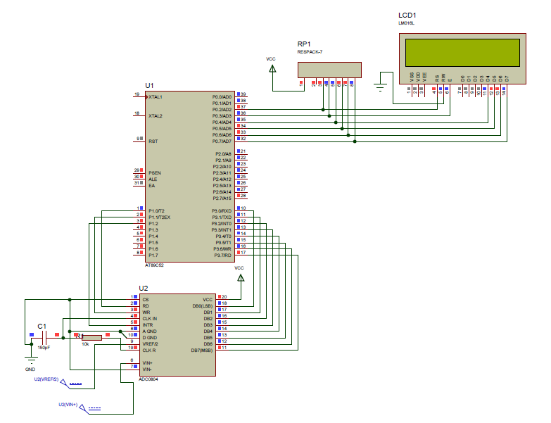
Then draw the circuit diagram as we want .In that circuit diagram decide how and where the Pin of LCD connect with PIC16f877 .
Here I used 4-bit lcd interfacing (to know more click here. )
circuit drawn .
So we want to write program in accordance with the above circuit.
So we want to write program in accordance with the above circuit.
In Mikro c there is library for interfacing the LCD it is very simple .
First the Pin number of the PIC change to a understandable one for that we do as follows .sbit LCD_RS at RB4_bit;
The above line of code means that the compiler changes RB4 pin of the PIC to LCD_RS . after the initialization of the above code the RB4 is called as LCD_RS through the program. So the PINs are configuring as follows .
- sbit LCD_RS at RB4_bit; // PIN name Changed
- sbit LCD_EN at RB5_bit;
- sbit LCD_D7 at RB3_bit;
- sbit LCD_D6 at RB2_bit;
- sbit LCD_D5 at RB1_bit;
- sbit LCD_D4 at RB0_bit; Then the Port PB is makes as output the following code is needed . The compiler recognize it as output
- sbit LCD_RS_Direction at TRISB4_bit; // making output
- sbit LCD_EN_Direction at TRISB5_bit;
- sbit LCD_D4_Direction at TRISB0_bit;
- sbit LCD_D5_Direction at TRISB1_bit;
- sbit LCD_D6_Direction at TRISB2_bit;
- sbit LCD_D7_Direction at TRISB3_bit;
Next step is to initialize the LCD . .
void Lcd_Init();
It means that the compiler tells how the PIC connect to the LCD
that is the PIN renaming , what type of LCD Modes (8bit or 4bit ) etc .
Next Step is giving the LCD Command by using LCD_Command function (ie Lcd_Cmd() .
which decide how the lcd shows look the command below .

for example to clear the LCD we put the following function
Lcd_Cmd(_LCD_ClEAR);
To write Messages on LCD dispaly we use the following simple function
void Lcd_Out(char row, char column, char *text);
For example Write text "Hello!" on Lcd starting from row 1, column 3:
Lcd_Out(1, 3, "Hello!");
It means the first Number "1" the starting row .ie first line
The secind Number specify the starting position of column .
the Last one is the message .
Another helpful function is
void Lcd_Out_Cp(char *text);
Example : Lcd_Out_Cp("Here!");
It uses to display the text message at the current position .
void Lcd_Chr(char row, char column, char out_char);
The above function is used to display the value which is placed in variable
Example : Lcd_Chr(2, 3, 'i');
It displays the 'I" value in the second line at the third position .
sbit LCD_RS at RB4_bit;
sbit LCD_EN at RB5_bit;
sbit LCD_D4 at RB0_bit;
sbit LCD_D5 at RB1_bit;
sbit LCD_D6 at RB2_bit;
sbit LCD_D7 at RB3_bit;

sbit LCD_RS_Direction at TRISB4_bit;
sbit LCD_EN_Direction at TRISB5_bit;
sbit LCD_D4_Direction at TRISB0_bit;
sbit LCD_D5_Direction at TRISB1_bit;
sbit LCD_D6_Direction at TRISB2_bit;
sbit LCD_D7_Direction at TRISB3_bit;


 void main()

   {
      Lcd_Init();
      Lcd_Cmd(_LCD_Clear);
      Lcd_Cmd(_LCD_CURSOR_OFF);

      Lcd_out(1,1,"Hello");

      while(1)
      {}

   }
Full Project Can be download here Including Proteus File click