Rotation Counter using 8051
I need to make a counter for a transformer winding machine .In that the winding is made by hand . so the roation need to be keep in mind ,that is too much difficult .So the winding shaft rotaion counting by an infrared sensor module which is connected with 89S52 microcontroler and a LCD .
Infrared based Rotation Counter by 805 or (contact less Rotation Counter or Rotation counter without using Interrupt.


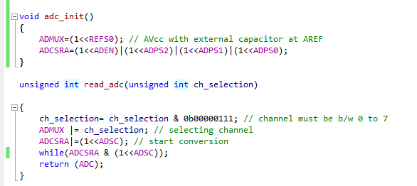
Code :

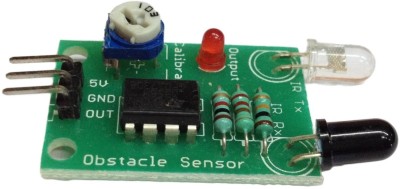
INFRARED Module
Download the Full Project CODE and with Proteus Here