int main(void) { int a; struct menu s1= {0}; //s1.menu_up-key =1; const char *menu_display[10]; menu_display[0] = " Select Menu"; menu_display[1] = " Set Time"; menu_display[2] = " Set Date"; menu_display[3] = " Set Alaram"; menu_display[4] = " Set Alaram "; //sub menu menu_display[5] = " Enter Time "; menu_display[6] = " Enter Date "; menu_display[7] = " Enter Alarm "; menu_display[8] = " Enter Alarm"; LCD_SetUp(PB_0,PB_1,PB_2,P_NC,P_NC,P_NC,P_NC,PB_4,PB_5,PB_6,PB_7); LCD_Init(2,16); LCD_GoToLine(0);
void menu_key_display(struct menu s1,const char *menu_display[]); void UP_Down_Keyvalue(struct menu s1,int i,int j);
/* Function Key Value For get key */ int Key_pressed(void) { while(1){ if (LEFT_S) { while(LEFT_S);return 1; } if (RIGHT_S){ while(RIGHT_S);return 2; } if (UP_S) { while(UP_S); return 3; } if (DOWN_S) { while(DOWN_S);return 4 ; } if (OK_S) { while(OK_S);return 5 ; } } }
/* Function Key Value For Up Key & Enter*/
void menu_key_display(struct menu s1,const char *menu_display[]) { int ch; int a; int menu_position =0; LCD_DisplayString(menu_display[menu_position]); do{
a = s1.menu_side_key; switch(a) { case 1: // set time { LCD_Clear(); LCD_GoToLine(0); LCD_DisplayString(menu_display[5]); LCD_GoToLine(1); LCD_DisplayString(" HH:MM:SS:PM/AM"); UP_Down_Keyvalue(s1,2,4); break; } case 2: // Set date { LCD_Clear(); LCD_GoToLine(0); LCD_DisplayString(menu_display[6]); LCD_GoToLine(1); LCD_DisplayString(" DD:MM:YY"); UP_Down_Keyvalue(s1,2,3); break; }
case 3: // set alarm { LCD_Clear(); LCD_GoToLine(0); LCD_DisplayString(menu_display[7]); LCD_GoToLine(1); LCD_DisplayString(" HH:MM:SS:AM/PM"); UP_Down_Keyvalue(s1,2,4); break; } case 4: // set alarm { LCD_Clear(); LCD_GoToLine(0); LCD_DisplayString(menu_display[8]); LCD_GoToLine(1); LCD_DisplayString(" HH:MM:SS:PM/AM"); UP_Down_Keyvalue(s1,2,4); break; } }
while(Key_pressed()!=5);
}
/* Function Key Value For UP_Down Key */ void UP_Down_Keyvalue(struct menu s1,int i,int j) {
An External Pulse Counter Using 8051 and Dispalying on 16x2 LCD
A circuits which is used to count the external pulses And which is displaying on an 16x2 LCD display . You can simply use this project for various purpose .It is a default project for counting Purpose.
Tutorials : -
To use 16 Bit counter we need to configure some register in 8051 as follows
TMOD Register is need to configure as follows
16 bit counter Setting with timer 0
TMOD=0x05; // Giving 0x05 it configured so .
8051 has Two Timer (each has 16 bit ) i am taking here Timer 0 It has to part First 8 bit (TL)) and the second part is (TH0) .
This timer is using to store the Pulses from the external (ie it will increment up to 65535 or FFFF)
TL0 = 0; // that timer clearing
TH0 = 0; // that timer clearing TR0 = 1 // TR0 setting to start the counting . Done ................................. After setting the above register as said the resulted value (counting value ) will save periodically in TL0 and TH0 . That value displaying after converting it to decimal . for LCD Tutorials Go Here
Download Her the all Project Including Proteus file Click Here
An External Pulse Counter Using 8051 and Dispalying on 16x2 LCD
A circuits which is used to count the external pulses And which is displaying on an 16x2 LCD display . You can simply use this project for various purpose .It is a default project for counting Purpose.
Tutorials : -
To use 16 Bit counter we need to configure some register in 8051 as follows
TMOD Register is need to configure as follows
16 bit counter Setting with timer 0
TMOD=0x05; // Giving 0x05 it configured so .
8051 has Two Timer (each has 16 bit ) i am taking here Timer 0 It has to part First 8 bit (TL)) and the second part is (TH0) .
This timer is using to store the Pulses from the external (ie it will increment up to 65535 or FFFF)
TL0 = 0; // that timer clearing
TH0 = 0; // that timer clearing TR0 = 1 // TR0 setting to start the counting . Done ................................. After setting the above register as said the resulted value (counting value ) will save periodically in TL0 and TH0 . That value displaying after converting it to decimal . for LCD Tutorials Go Here
Download Her the all Project Including Proteus file
Click Here
A Timer is device it sense thetime intervaland produce an output at a set value . example alarm Timer setting.(Timer in Wikipedia )
,What is the need of a timer in Micro controller ?
1) Some time micro controller Code need some accurate Delay ( Example blinking An LED in each accurate 1 sec. Look LED Blinking example
2)Some Time the code needs the code Repeat
3) Most of the Interfacing devices with micro-controller needs a clock (accurate interval of clocks) Example: LCD module require Clock Signal Look LCD Interfacing
Timer in 8051
Also a Timer actually require a clock pulse (pling) .These pulse are given from controller (actually it is in software based not giving ) see below picture
8051 type controller has two Timer Timer 0 and Timer 1 (These two timer is the length of 16 bit ,0000 to FFFF ).These Timer is named as TR0 and TR1.
The Timer Setting/configuring can controlling by the TMOD register
These TMOD register Values is used to decide how the Timer Works .
A Timer is device it sense thetime intervaland produce an output at a set value . example alarm Timer setting.(Timer in Wikipedia )
,What is the need of a timer in Micro controller ?
1) Some time micro controller Code need some accurate Delay ( Example blinking An LED in each accurate 1 sec. Look LED Blinking example
2)Some Time the code needs the code Repeat
3) Most of the Interfacing devices with micro-controller needs a clock (accurate interval of clocks)
Example: LCD module require Clock Signal Look LCD Interfacing
Timer in 8051
Also a Timer actually require a clock pulse (pling) .These pulse are given from controller (actually it is in software based not giving ) see below picture
8051 type controller has two Timer Timer 0 and Timer 1 (These two timer is the length of 16 bit ,0000 to FFFF ).These Timer is named as TR0 and TR1.
The Timer Setting/configuring can controlling by the TMOD register
These TMOD register Values is used to decide how the Timer Works .
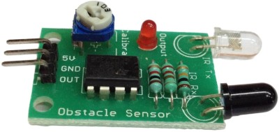
I need to make a counter for a transformer winding machine .In that the winding is made by hand . so the roation need to be keep in mind ,that is too much difficult .So the winding shaft rotaion counting by an infrared sensor module which is connected with 89S52 microcontroler and a LCD .
Infrared based Rotation Counter by 805 or (contact less Rotation Counter or Rotation counter without using Interrupt.
Code :
INFRARED Module
Download the Full Project CODE and with Proteus Here
Microcontrolers may not in Human thinking frequency .Human thinking frequency is lies in some of low Hz . Microcontroler works variety range of frequency ie ,12Mhz,20 Mhz etc . In a push Button micro controller interfacing, Human and Micro controller are feels that whether the push is pressed or not in different way as follows in the graph .
Some small duration pulse due to denounce generated as multiple touch error Hardware solution
It can be made by a resistor and a capacitor in the following manner or any other for comfortable
When ever the switch is pressed the capacitor will charge rapidly ,practically the first charge wil be across the ,capacitor ,
So we can avoid the denouncing effect .
The capacitor and the resistor will be select in accordance with time constant . as follows
74HC138 is a decoder of the type octal 3- to- 8 Line Decoder / Demulator and Inverter.
The chip enables 3 pins - A, B and C - to output 8-bit , meaning that decodes three address lines in 8 possible ways . Simple, with 3 input bits to form 8 Address : 2 3 = 8; See the truth table:
An address decoder is also called a " demultiplexer " or " demux " . Although these terms are more generic and can refer to devices other than decoders addresses, TTL 74138 mentioned here can be called " demux 3- to -8" .
Decoders addresses are fundamental building blocks for systems using bus bars. They are represented in all families of integrated circuits and all the standard libraries FPGA and ASIC . They are discussed in introductory texts in digital logic design